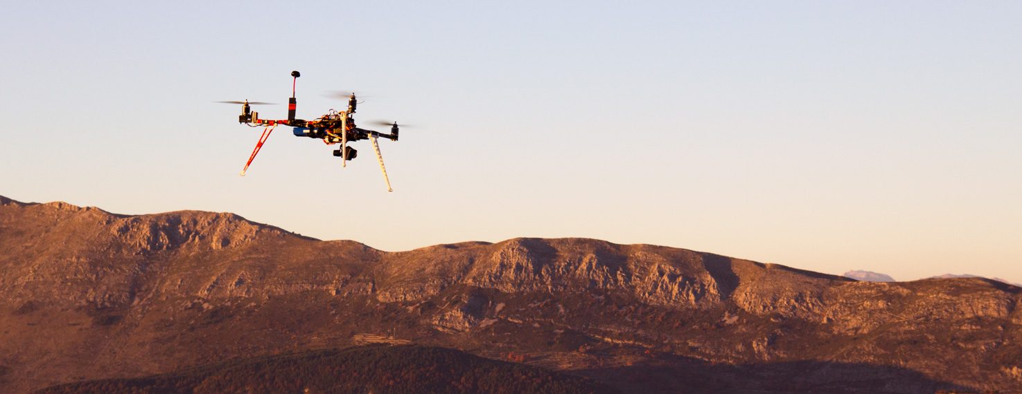
In this post, I describe how I designed and built the Quadcopter V1. This quadcopter is inspired from the Tricopter V2.5 (which is a remix of the RCExplorer tricopter). Some parts such as the arms, the motor mounts and the landing-gear are the same. The most important novelty is the use of the APM 2.5 board (with ArduPilot, an open source software) and a GPS which enable semi-automatic and automatic flight modes (such as flying given a straight line, performing automatic panorama, following a pre-programmed waypoint track, returning to launch in case of signal lost..). These flight modes are really interesting to get better video footages. The video performances are also improved by the use of a 3 axis gimbal.
I want to thank the SoFAB for helping me in the realization of this project, enabling me to manufacture the quadcopter parts.
Here is a summary of the drone characteristics and components used in this configuration:
- Frame: Self-designed, made out of plywood and PMMA cast
- Arms: Square carbon booms (10x10x325mm)
- Flight Controller: APM 2.5 (RCTimer)
- GPS: u-Blox CN06 Plus (RCTimer)
- Motors: T-Motor MT2216-12 V2 800KV
- ESC: Favourite Littlebee 30A (BLHeli)
- Props: Graupner E-Prop 10×5
- Battery: Zippy 4S 5000mAh 20C
- RC/TX: Graupner MX-16 HoTT / GR-16 receiver
- Video TX: ImmersionRC 5.8Ghz 600mW and ImmersionRC SpiroNET antennas
- FPV Goggles: Fatshark Attitude V2
- Camera: GoPro 3 Black
- Gimbal: DYS Smart3
- All up weight: 1790 grams (including battery and GoPro camera)
- Flight time : ~ 15 minutes
The design files and the list of all the components used to build the drone are available on Thingiverse.
In this post, I will then:
- present an overview of the electronic components used
- introduce the frame design on SolidWorks
- describe the build
- detail the ArduPilot configuration
- show some pictures and videos of the quadcopter flying
Overview of the electronic components used
Let's first have an overview of the electronic components used to build the drone.
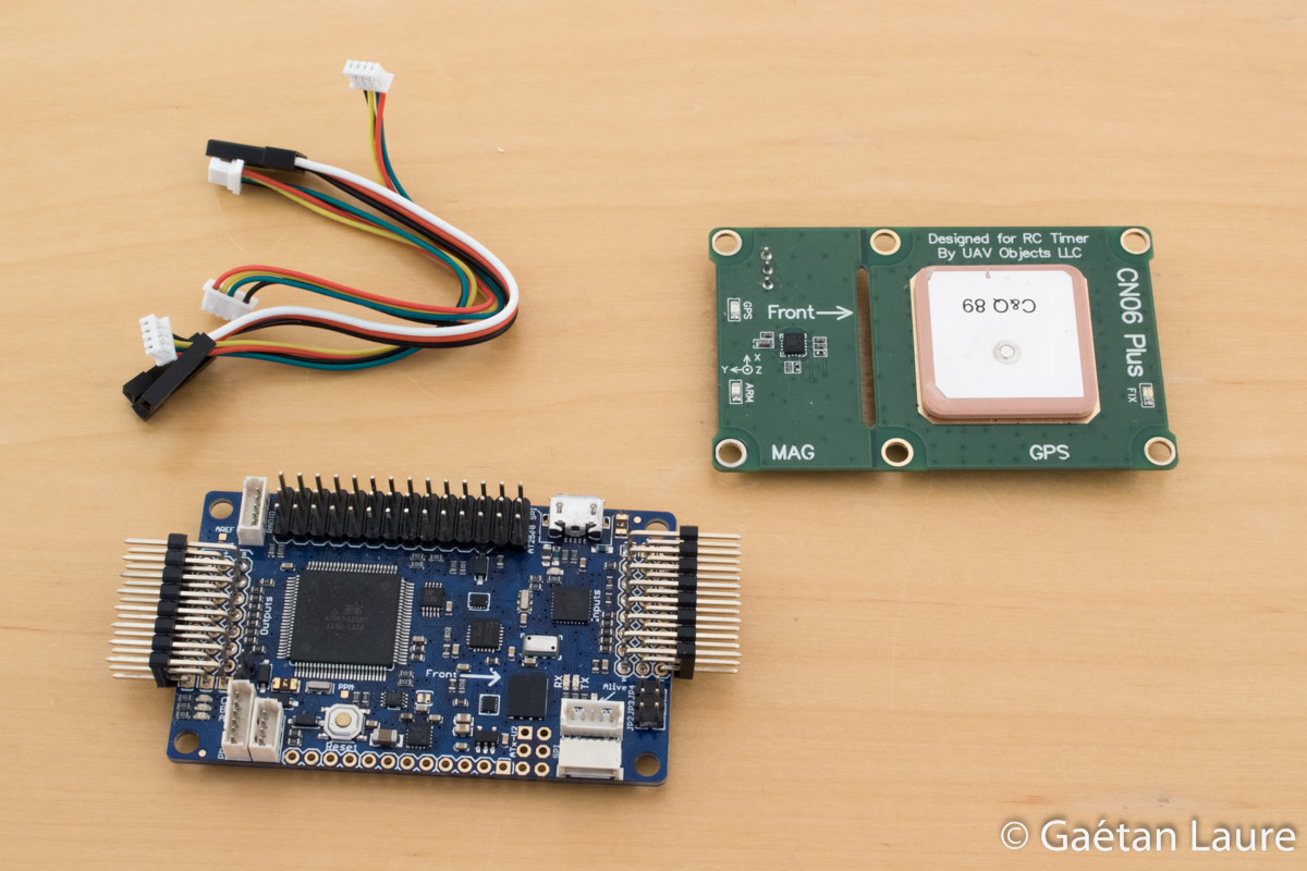
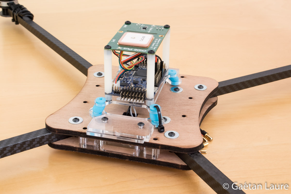
The flight controller used is the APM 2.5 (ArduPilot Mega) from RCTimer (APM 2.5 documentation). The architecture is quite close to the Arduino Mega (same processor), but the board has, in addition, all the sensors needed to fly a drone (3 axis accelero/gyro/compass and a barometer). It runs the ArduCopter open-source software which enables to configure, fly the drone and preform autonomous flights. The GPS used is designed to come over the top of the APM 2.5 (using standoffs). It also embeds an external compass (magnetometer). We are going to use this compass instead of the APM one in order to avoid interferences.
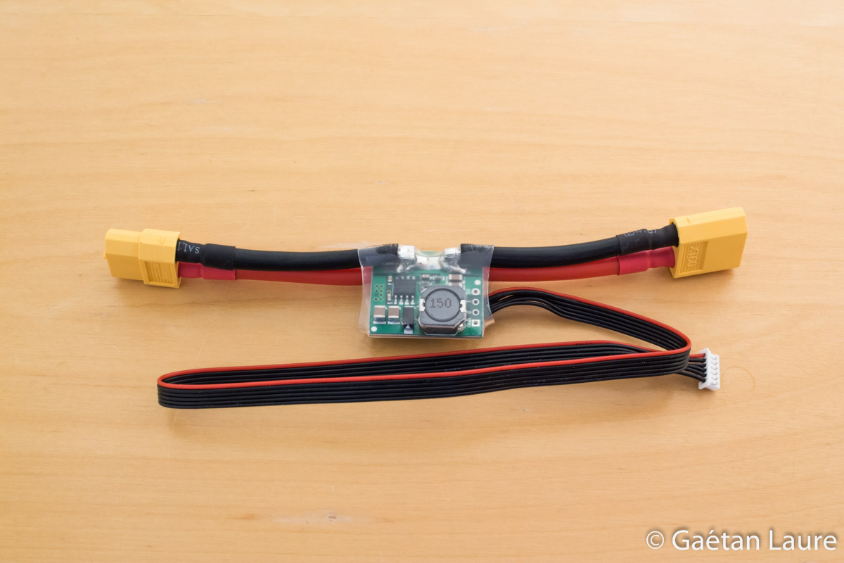
The APM 2.5 is powered using this power module (which is plugged on the battery). This power module also provides voltage and current measurements to the APM.
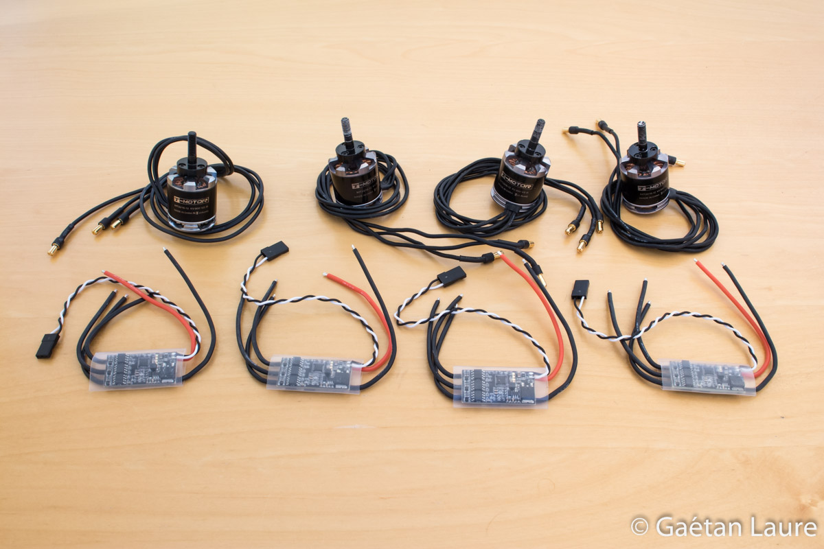
The motors are the same than on the Tricopter V2.5 (T-Motor MT2216-12 V2 800KV). The ESCs used are the Favourite Littlebee 30A (they come flashed with BLHeli 14.3, an open-source firmware, and can be configured, using this usb programming tool, from a computer).
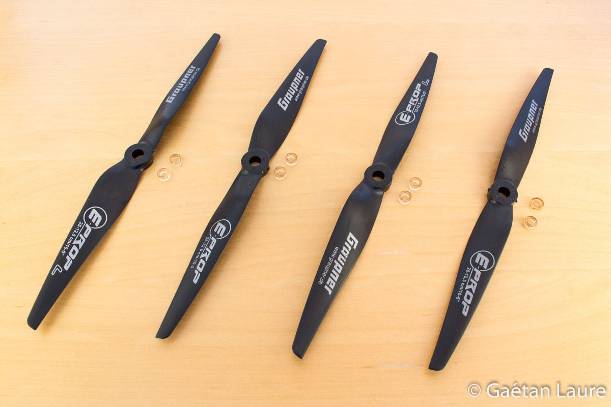
The props used are the Graupner E-Prop 10x5. They are stiff and come quite well balanced. These props are a bit expensive (7-8€ / prop) but they are nice to avoid having vibration and Jello effect in the video.
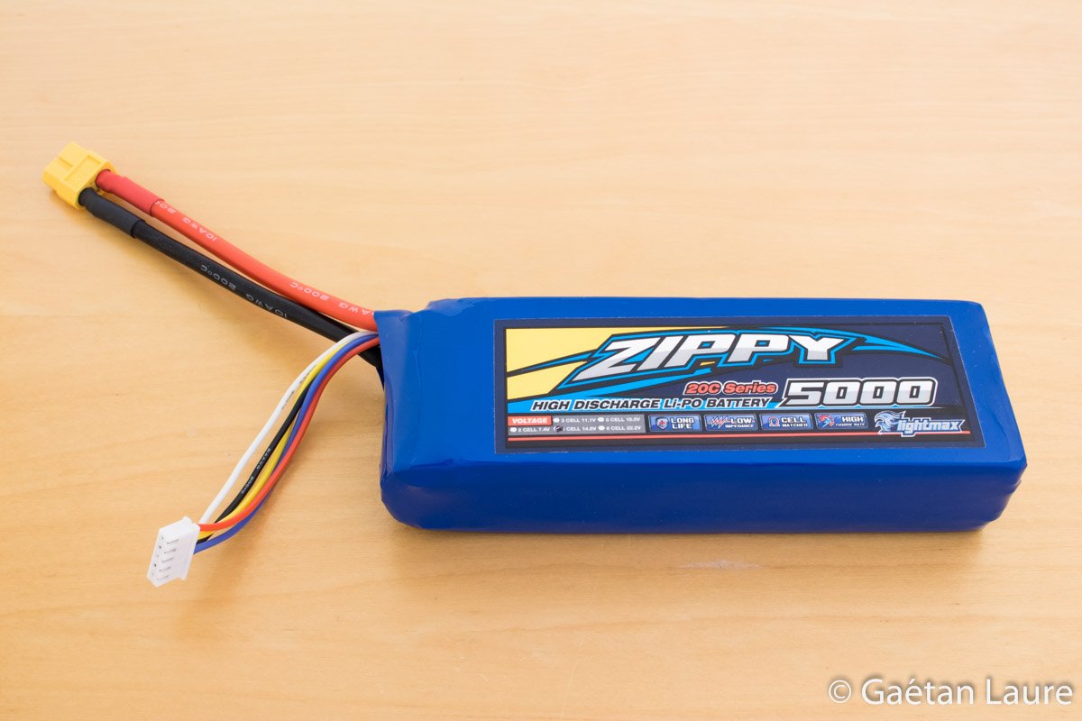
The drone is powered using a Zippy 4S 5000mAh LiPo battery (15.2 V nominal voltage). It weights 450 grams. I replaced the bullet battery connectors by an XT60 connector.
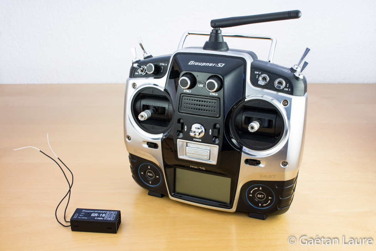
I still use the Graupner MX16-Hott radio controller and a GR-16 receiver to control the drone.
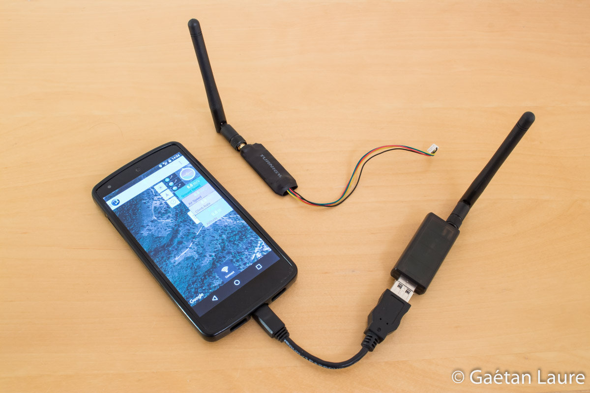
Information about the drone state (location, orientation, battery voltage...) are sent to a ground station (a computer or a smartphone) using these telemetry modules and the MAVLink protocol. A module is plugged into the APM board (using a serial interface), the other one is plugged to the ground station (here my smartphone with an OTG wire) through a USB port.
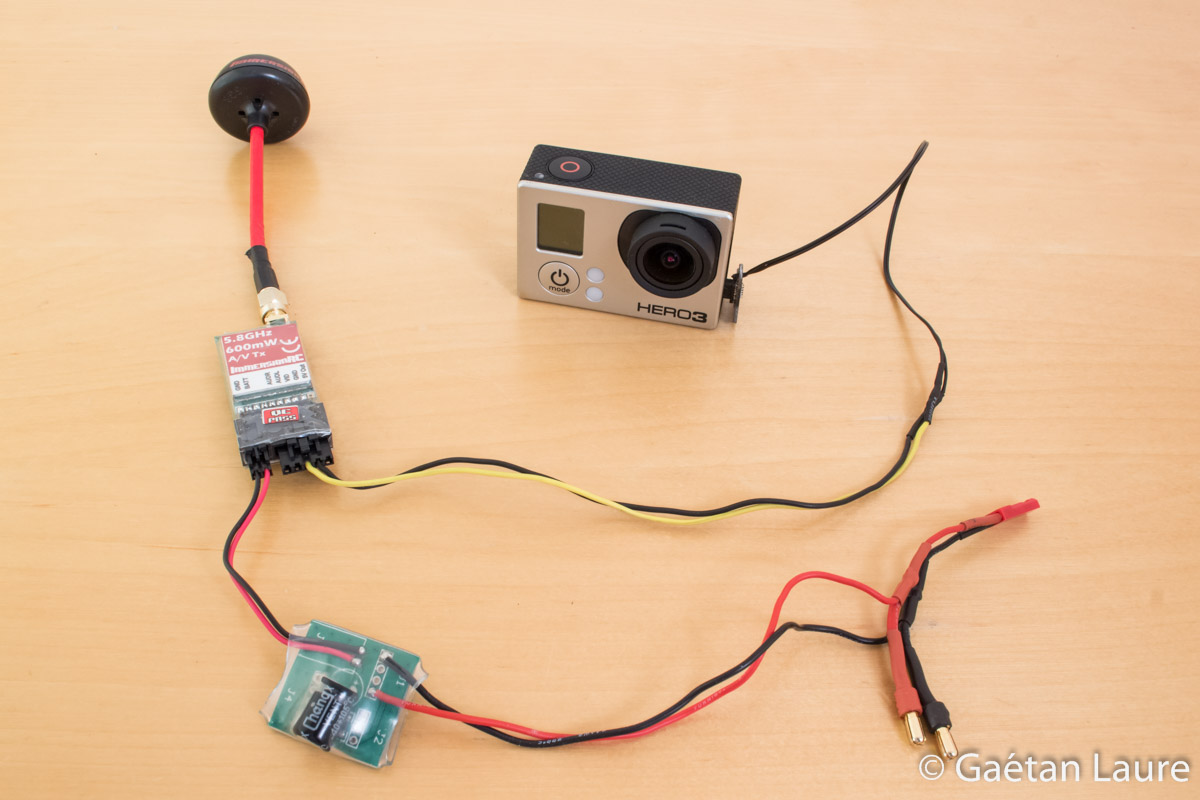
The camera used is a GoPro 3 Black. The video is transmitted to the ground using a 5.8GHz 600mW ImmersionRC transmitter with spiroNET antennas.
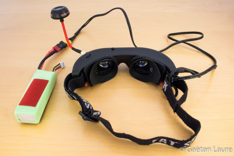
I receive the video signal through FatShark Attitude V2 goggles. Goggles are powered using a 3S 2200 mAh LiPo battery. With this setup, the video signal can be received up to 1 km range (without obstacle).
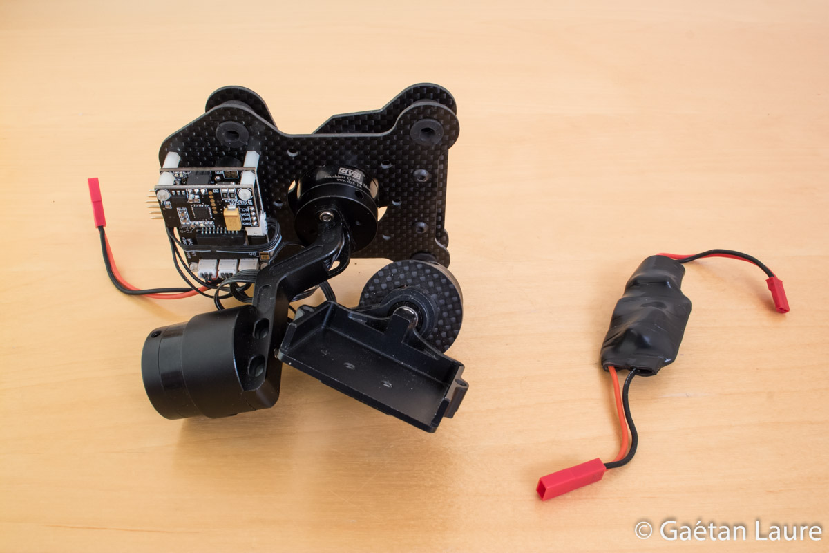
To stabilize the GoPro, I use the DYS smart3 3 axis gimbal. It has an IMU (Inertial Measurement Unit) and 3 brushless motor to perform stabilization around the roll, yaw and pitch axis. It features signal inputs, the GoPro pitch orientation can then be controlled from the ground using the radio controller. This gimbal weight 240 grams. I use a 12V regulator to adapt the LiPo battery voltage to the gimbal voltage range.

This is how all the components are going to be wired on the drone. The large green wires symbolize multiple wires. In the building part, I will mention precisely the APM ports used to connect all the components.
The frame design on SolidWorks
In this part, let's see how the quadcopter frame is designed. It has been CAD designed using SolidWorks. For this purpose, I created a virtual assembly of all the designed parts. The advantage of using this approach is that you can directly see if the different parts match correctly. You can also check if there is enough space to embed all the electronic components. Thus, CAD design enables to accelerate the prototyping phase, machining parts only at the end.
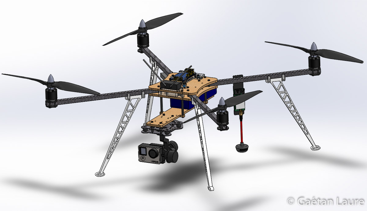
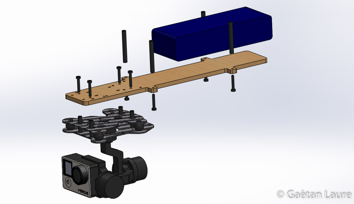
This is what the quadcopter design look likes. Some parts were taken from CAD libraries: the GoPro, the FPV transmitter and the flight controller are from grabcad.com. The landing gear (3D printed), the motor mounts and the arms are the same than the Tricopter V2.5. The parts specially designed for this quadcopter are in plywood and in PMMA cast (a kind of plexiglass). These materials can easily be cut by the Trotec Speedy 100 laser cutting machine I used at SoFAB.
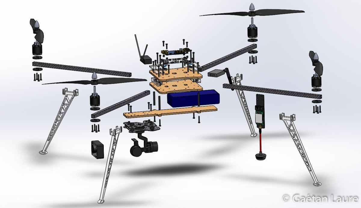
An exploded view to see how all the parts are laid out. The FPV transmitter and the telemetry module are mounted on the back arms using zip-ties. The motors are mounted on the arms using the circular motor mounts.
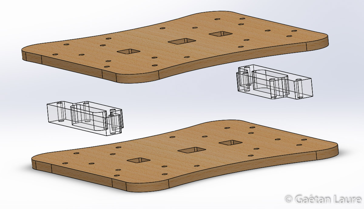
The two main parts of the frame are laser cut into 5mm plywood (okoume, 3 plies). They are separated by two spacers laser cut into 10mm PMMA cast sheet.

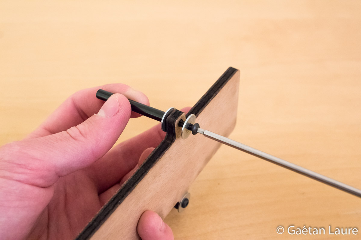
Carbon arms are assembled this way between the two main plates. They come into abutment with four screws.

Arms can be folded up, such as the tricopter 2.5, for easy transportation. It also absorbs shocks and prevents damage in case of a crash.
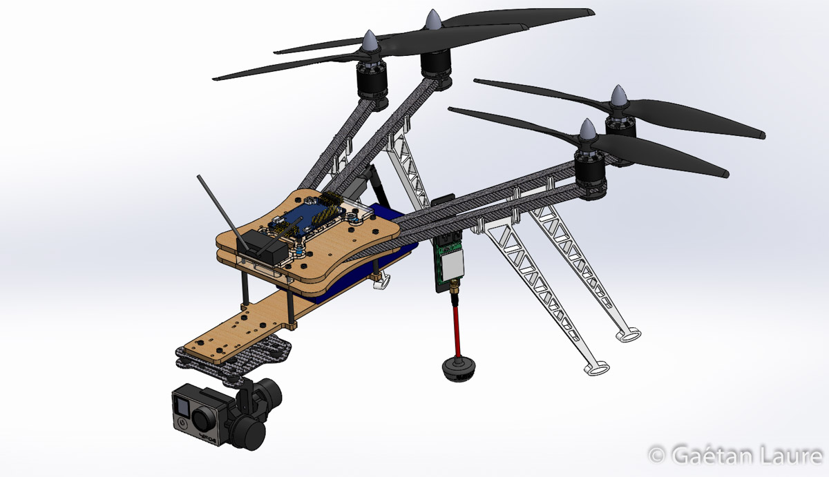
The drone folded up.

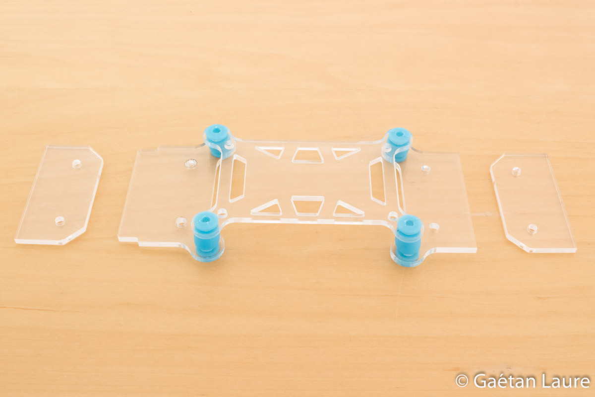
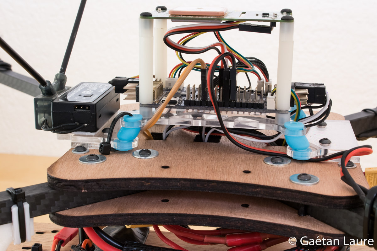
The APM 2.5 (in blue) is mounted on a vibration damping platform (laser cut into 3mm PMMA cast sheet). The APM accelerometers are then isolated from vibrations (coming from the motors) and provide less noisy data. Cyan small tubes represent the damping balls.
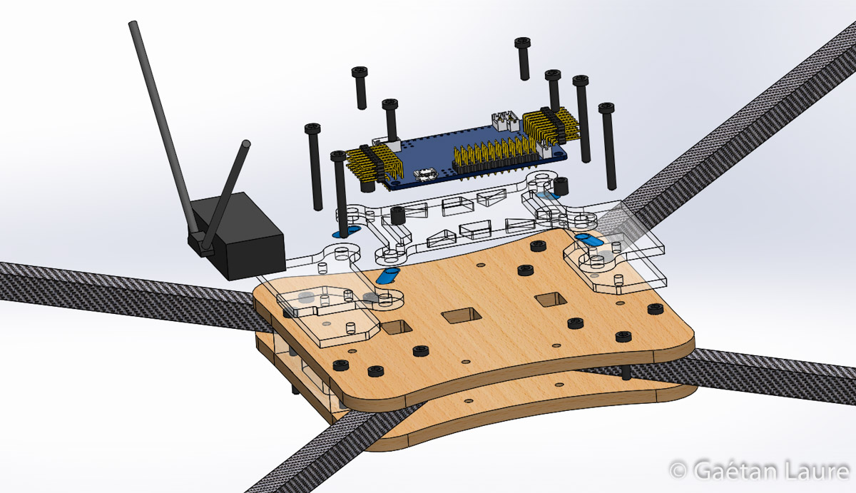
The vibration damping platform parts are assembled this way. The receiver (with the two antennas) is attached, using double-sided tape, on the front part of the platform.
The battery tray is mounted on the main frame using four standoffs. It carries the battery (in blue) and is designed to fit the DYS smart3 gimbal on it. It's laser cut into 5mm plywood such as the two main plates of the frame.
Building the drone
Let's now build the drone.
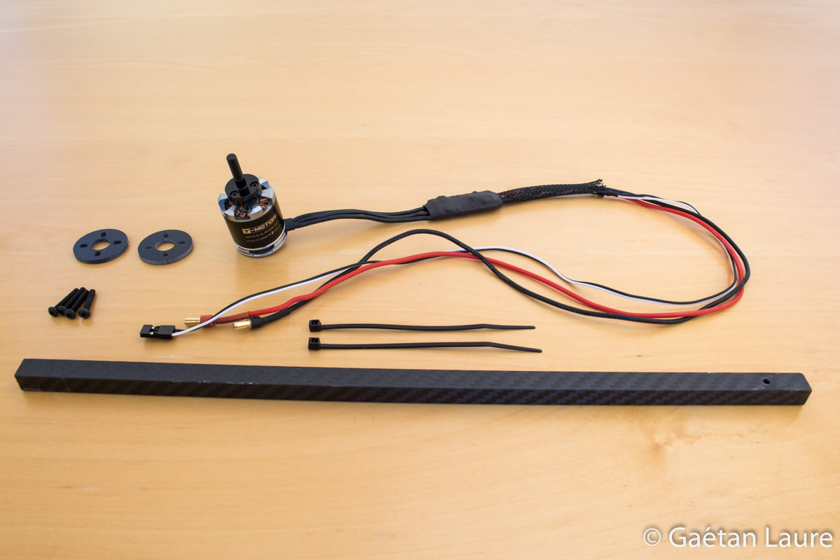
I first assemble the arms, the method is really close to the one described by RCExplorer. The procedure is the same for each arm. I start by wiring the ESCs and motors.
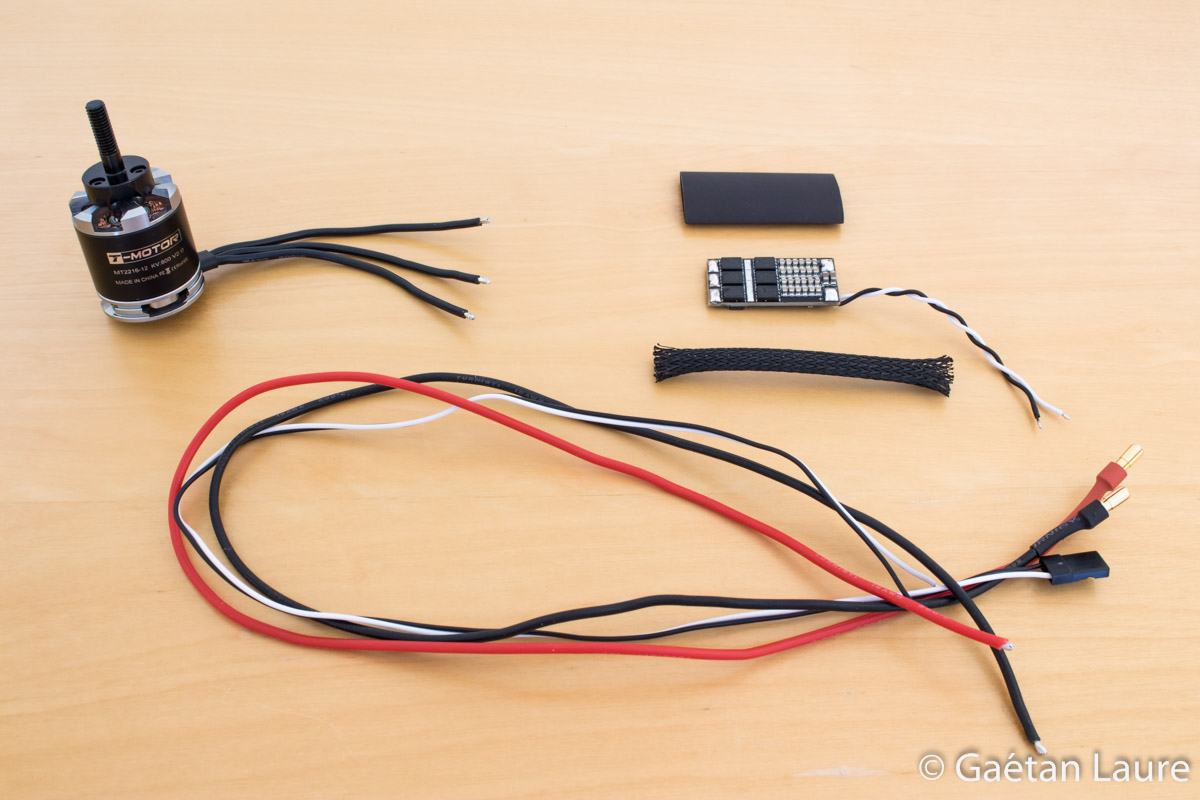
I have unsoldered the original ESC wires to solder longer ones. Power and signal wires have to be 50 cm long (the signal wires I used were only 43 cm long, so I'm going to solder them to the original wires). I soldered 4mm gold bullet connectors on the power wires. I cut the motor wires to a length of 8 cm.
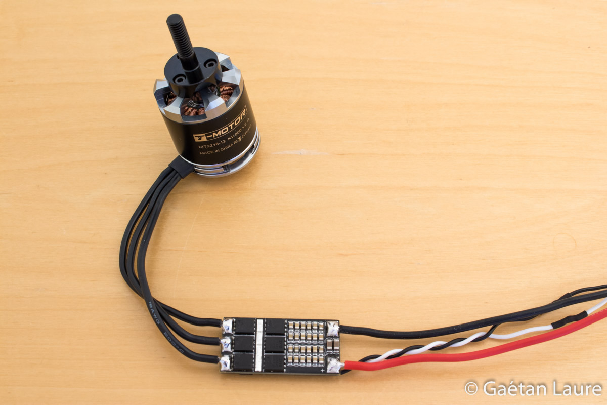
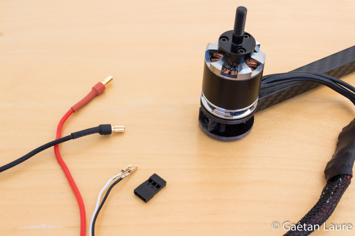
I first soldered the motor wires directly on the ESC. I don't use any connector to make the connection safer. Thanks to the BLHeli firmware flashed on the ESC, the motor direction of rotation can still be modified without permuting two wires. I also soldered the power and signal wires.
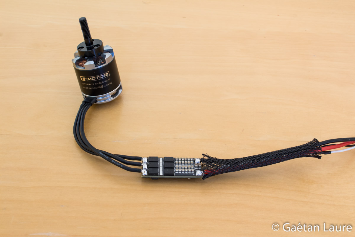
To protect the wiring, I slid 6mm wire mesh over the power and signal cables.

I put on some 14mm heat shrink to protect the ESC.
The motor and the ESC are ready to be mounted on the arm.

The motor is attached using the circle motor mounts and M3 18mm screws. I put threadlocker on the screws to avoid unscrew due to vibration. I screw a few turns at a time, describing a cross pattern, to get an equal tension on the four screws at the end.
I'm going to pull wires through the arms. To make it easier, I take servo wires out of the servo connector.
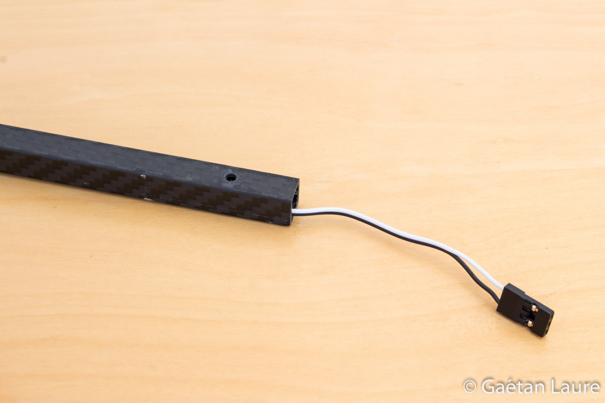
Servo wires pulled through the arm.
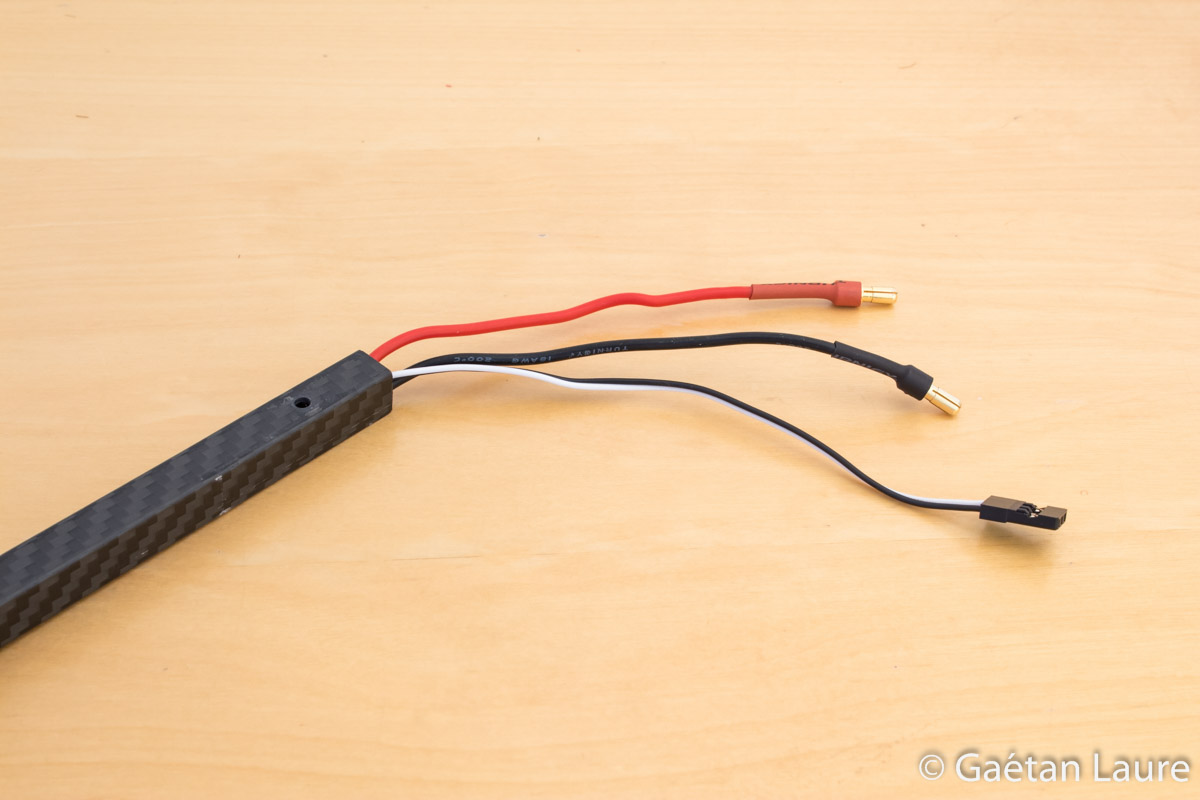
Power wires were pulled one by one. It's not so easy with the bullet connectors.
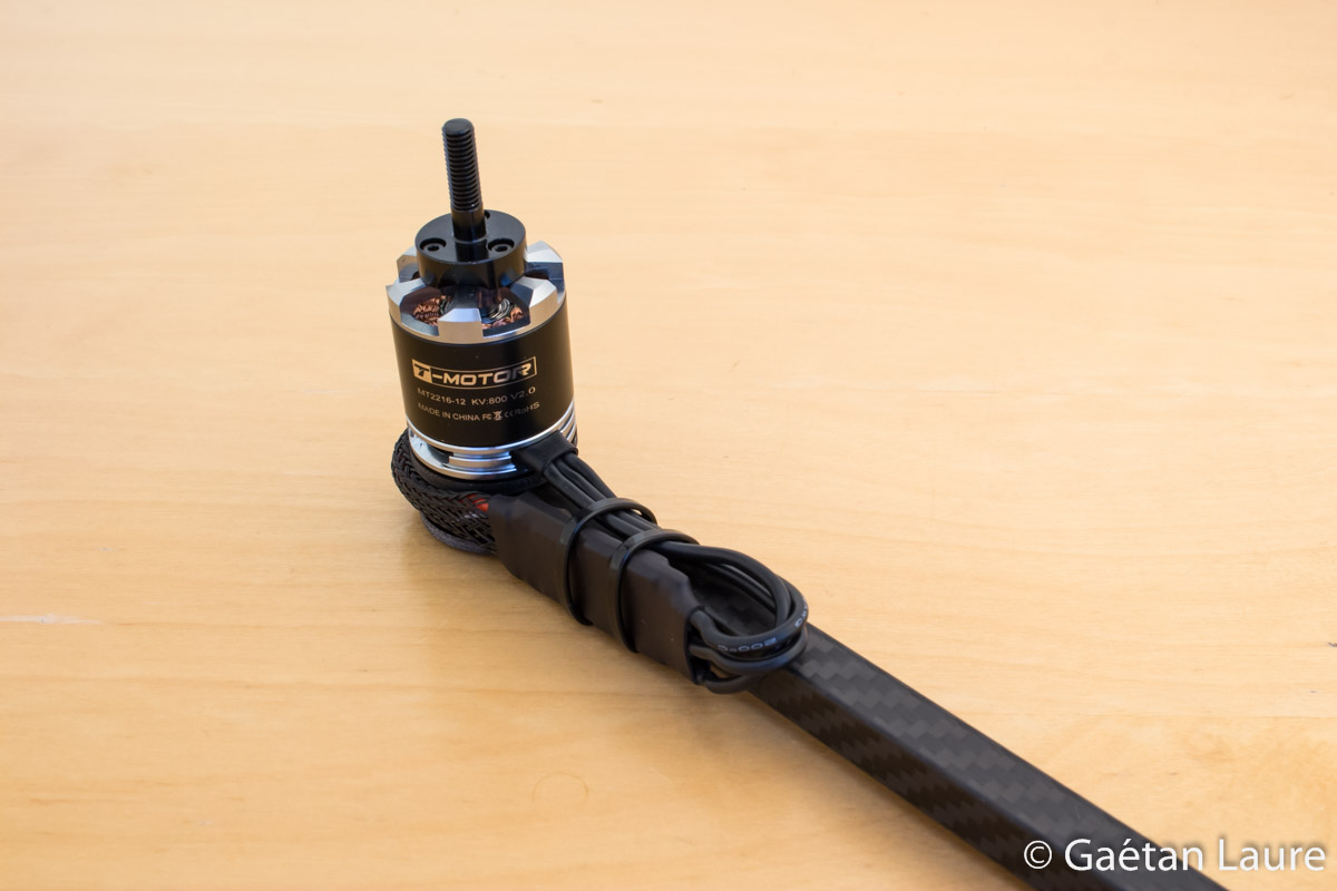
The ESC is finally mounted on the arm using zip-ties.
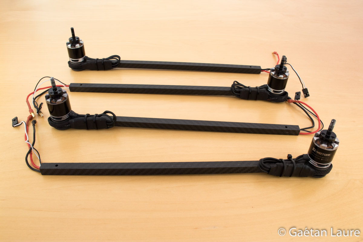
The four arms are ready to be fitted on the quadcopter frame. Note that the ESCs are mounted in opposite directions. They can then face backwards on the quadcopter and be better protected.
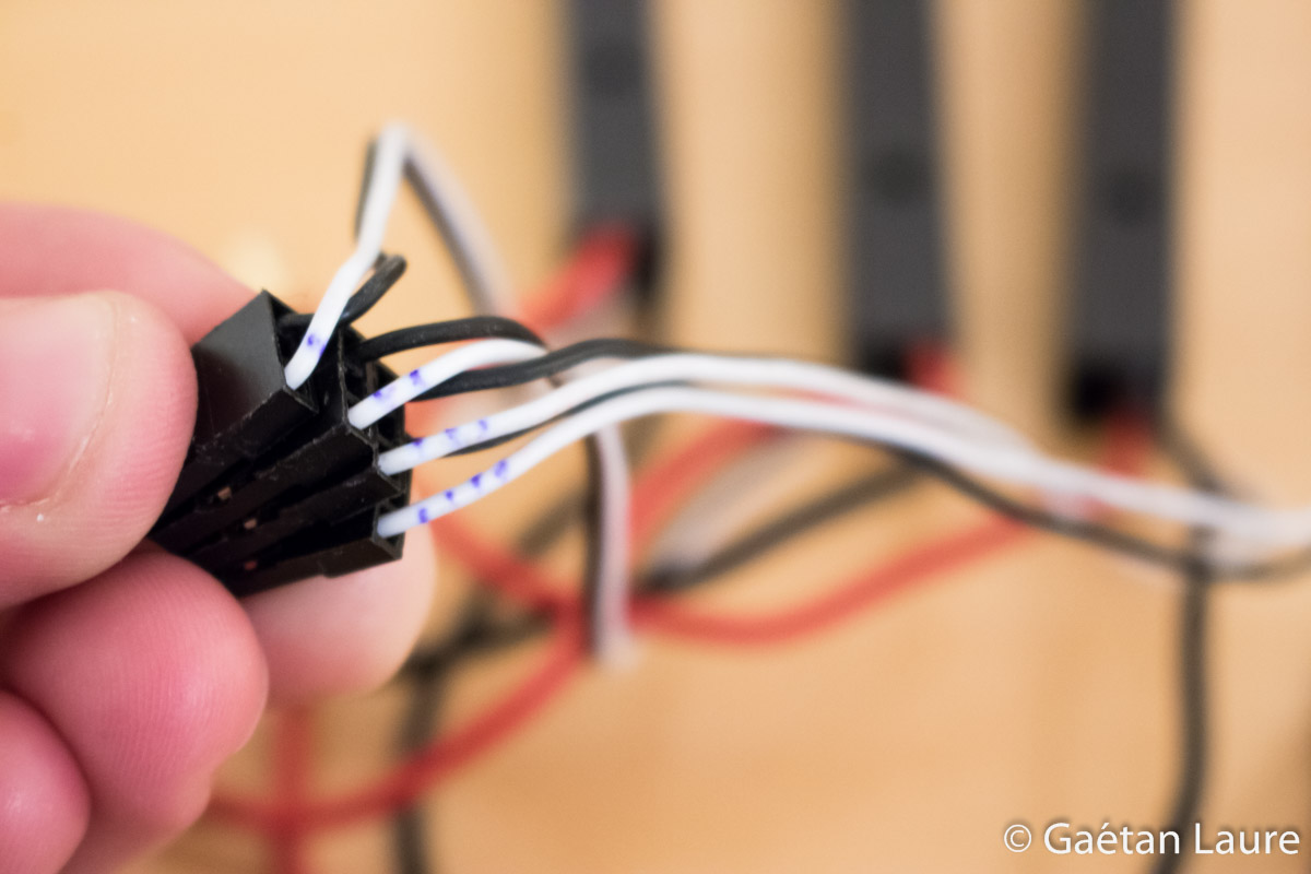
I number the signal wire to connect them in the correct order (to the APM) once arms will be installed.
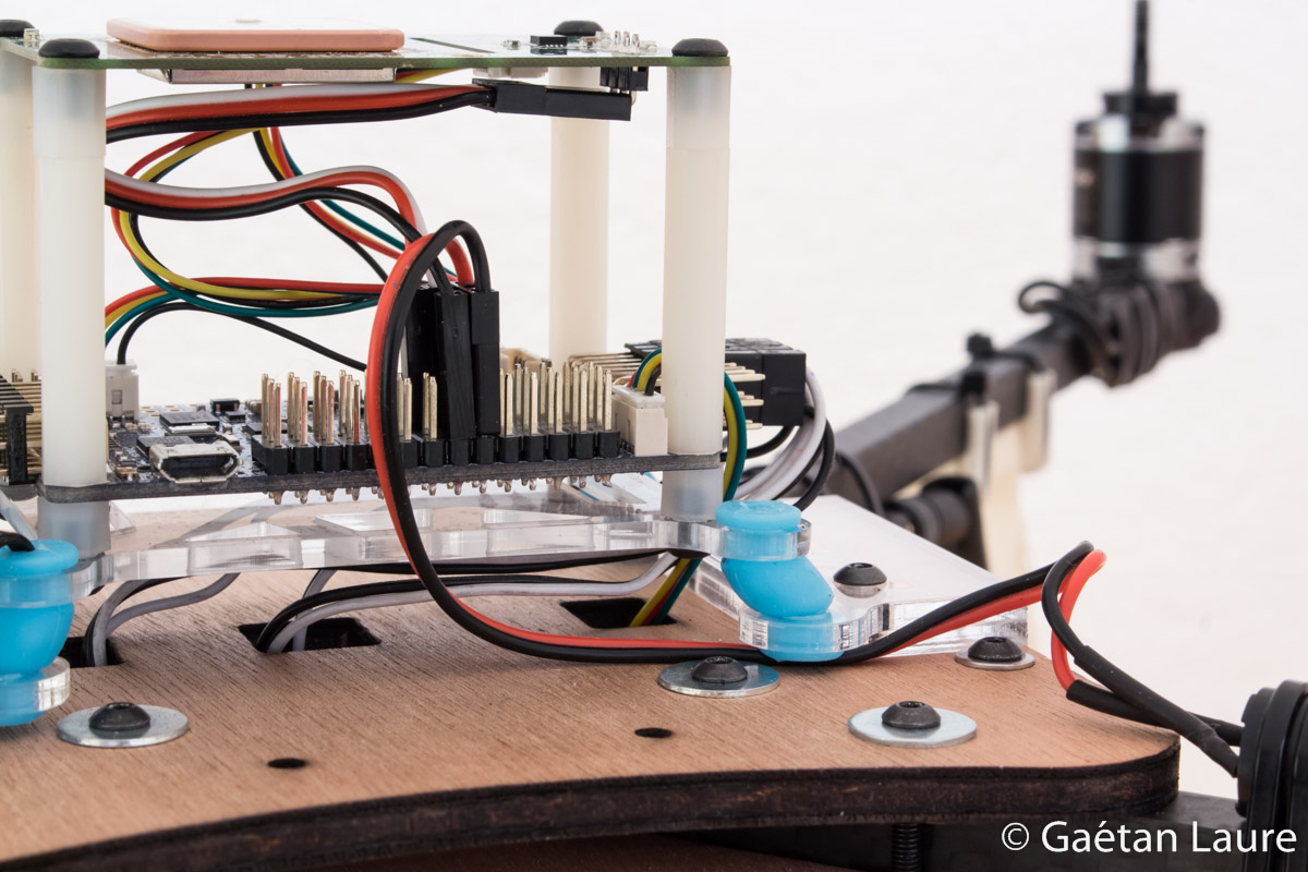
Let's now assemble the vibration damping platform and mount the APM board and the GPS on it.
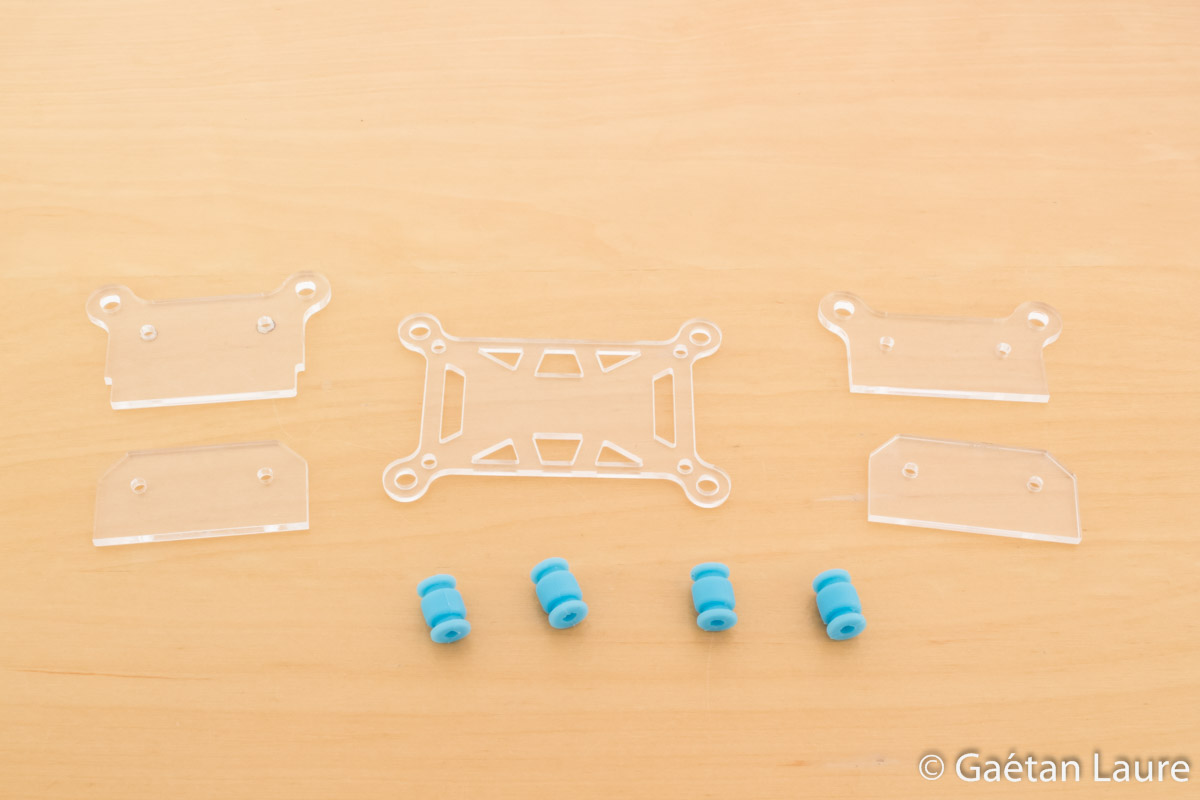
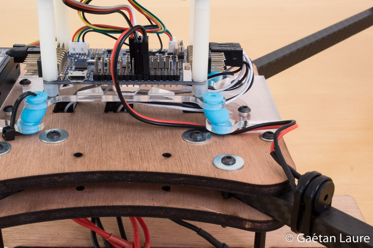
The vibration damping platform parts, laser cut into 3mm PMMA cast sheet, and the blue damping rubbers.
The damping rubbers installed.
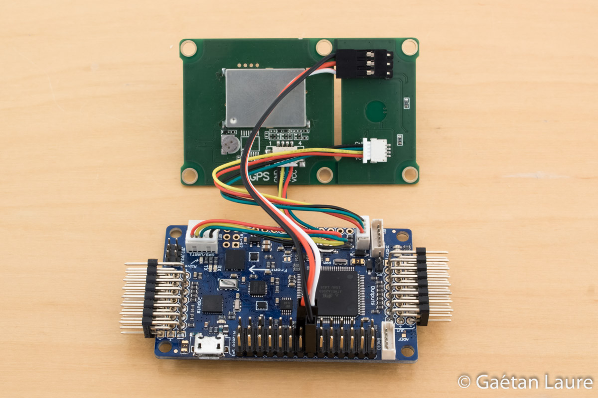
Wiring the APM and the GPS board. The compass is connected to the APM I2C port. The GPS is connected to the APM GPS port. GPS board LEDs are connected to A6 and A7 APM outputs.
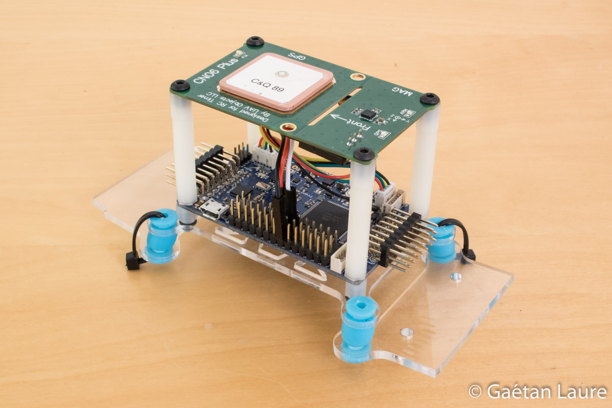
The GPS board is installed over the APM board using M3 30mm standoffs. I use plastic standoffs, instead of aluminium ones, to minimize interference on the external compass. I use small M3 5mm standoffs to mount both boards on the vibration damping platform. I use two zip-ties to prevent the boards to move away in case of a damping rubber break.
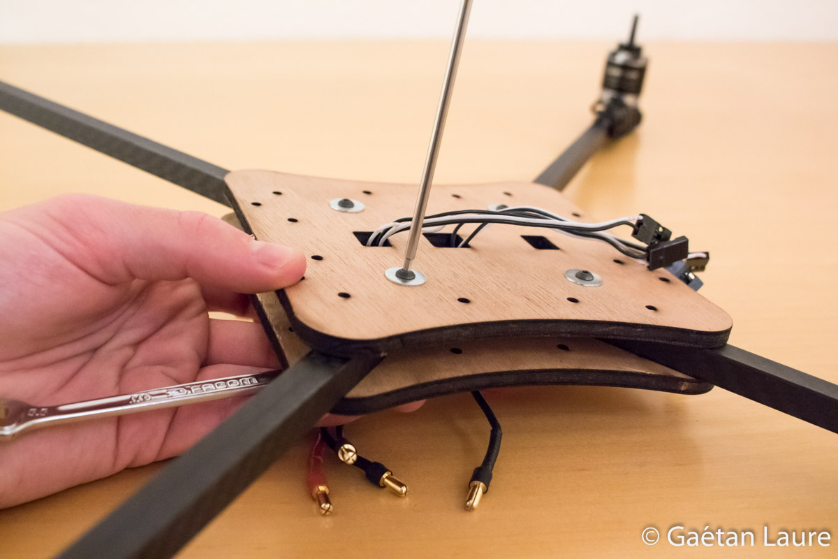
Let's now mount the arms and the vibration damping platform on the two main plates.

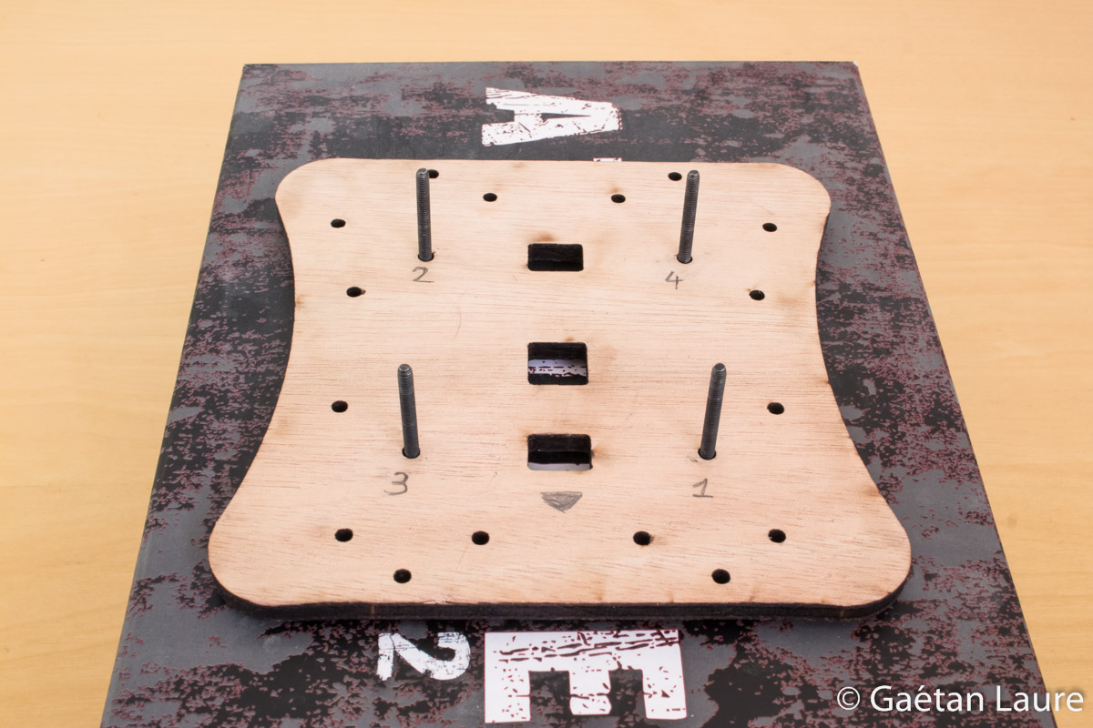
The two main plates and the spacers laser cut. I use twelve M3 30mm screws and lock nuts to mount the arms and the damping platform. I also use flat washers to tighten the screws without damaging the plywood.
The four first screw are installed like this on the top plate.
For the next steps, the top plate is positioned downward on a box.
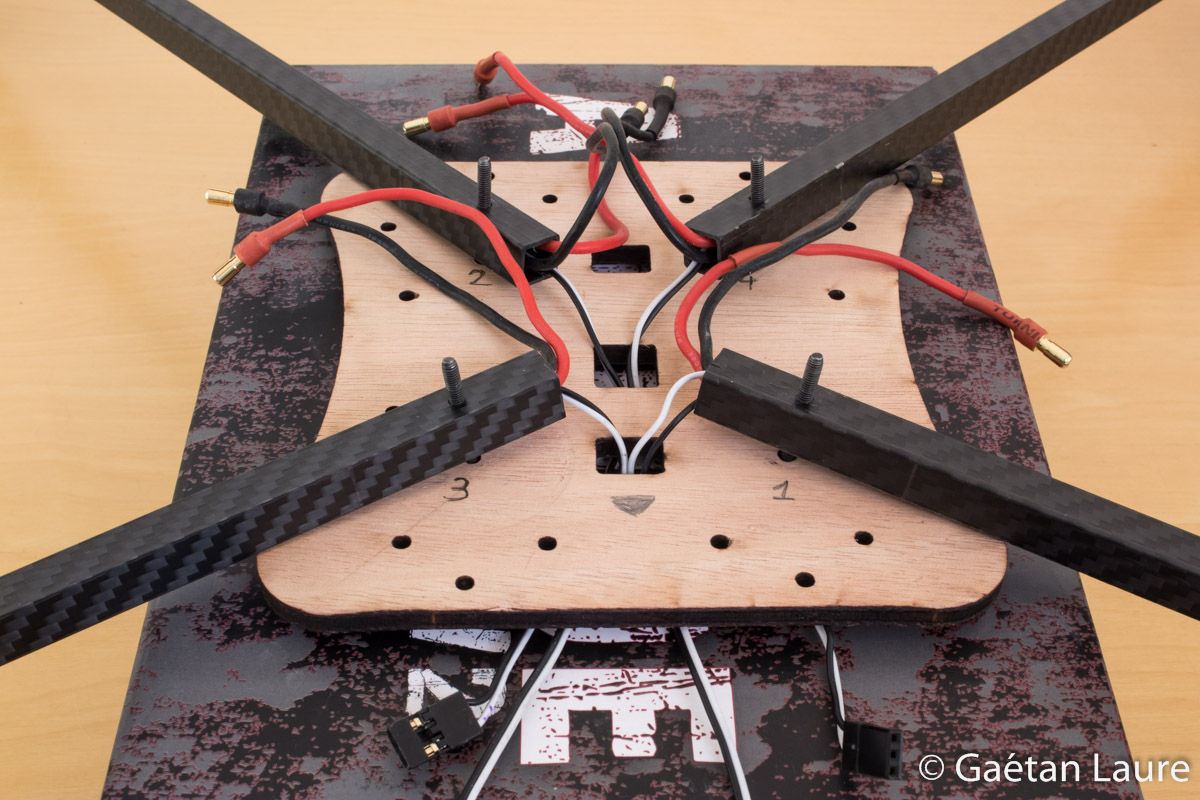
The arms are installed, given the numbers indicated on the top plate (to match ArduCopter ESC wiring for Quad X configuration), motors downward. The signal wires are pushed through two holes (the closest ones to the front of the plate).
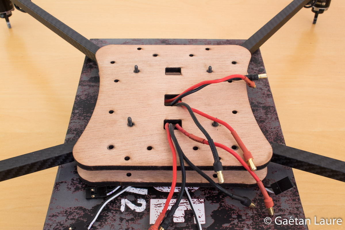
The bottom plate is then installed. The power wires are pushed through the corresponding two holes.
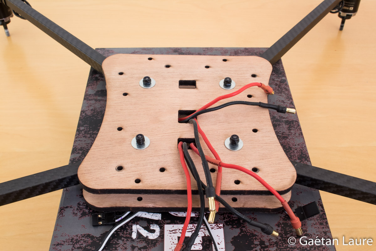
The flat washers and lock nuts are then placed.
And finally screwed.
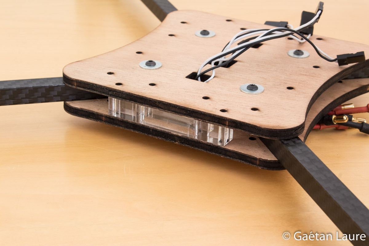
Spacers are inserted between the plates.
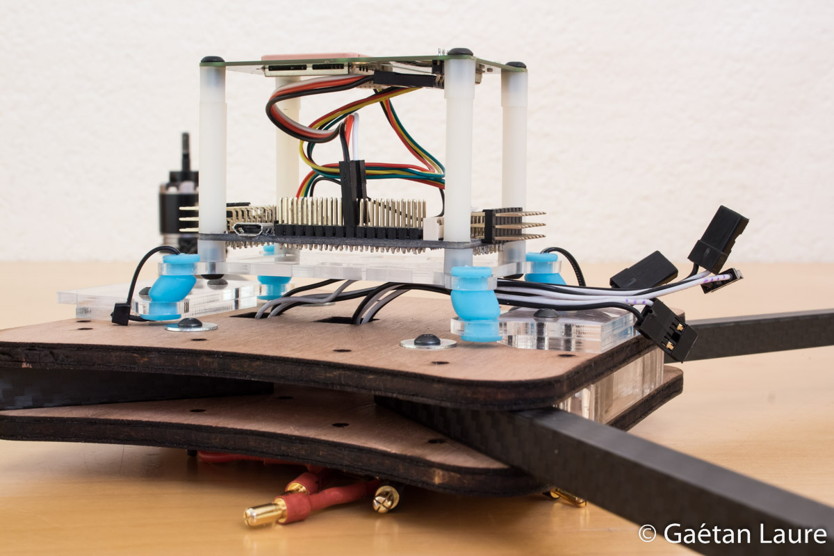
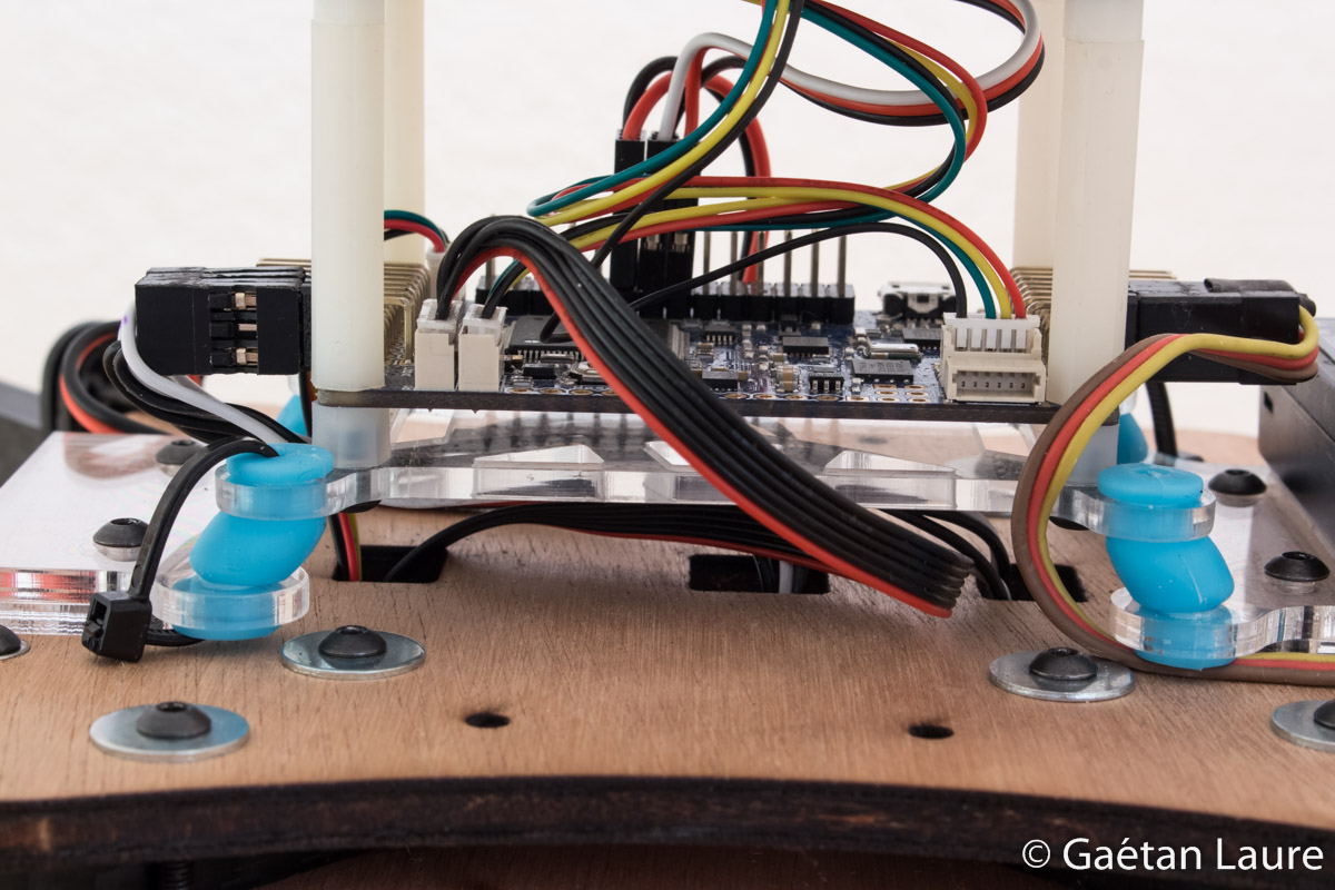
The vibration damping platform is then installed over the top plate (using four M3 30mm screws). The ESC signal wires pass under the vibration damping platform.
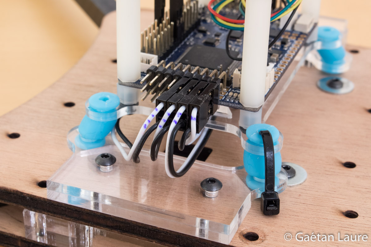
The ESC signal wires are connected this way, respecting the number order, on the APM board.
The last four screws are installed. The arms come into abutment these screws.
Under the bottom plate view.

Arms can be folded up like this without any difficulties concerning the wires.
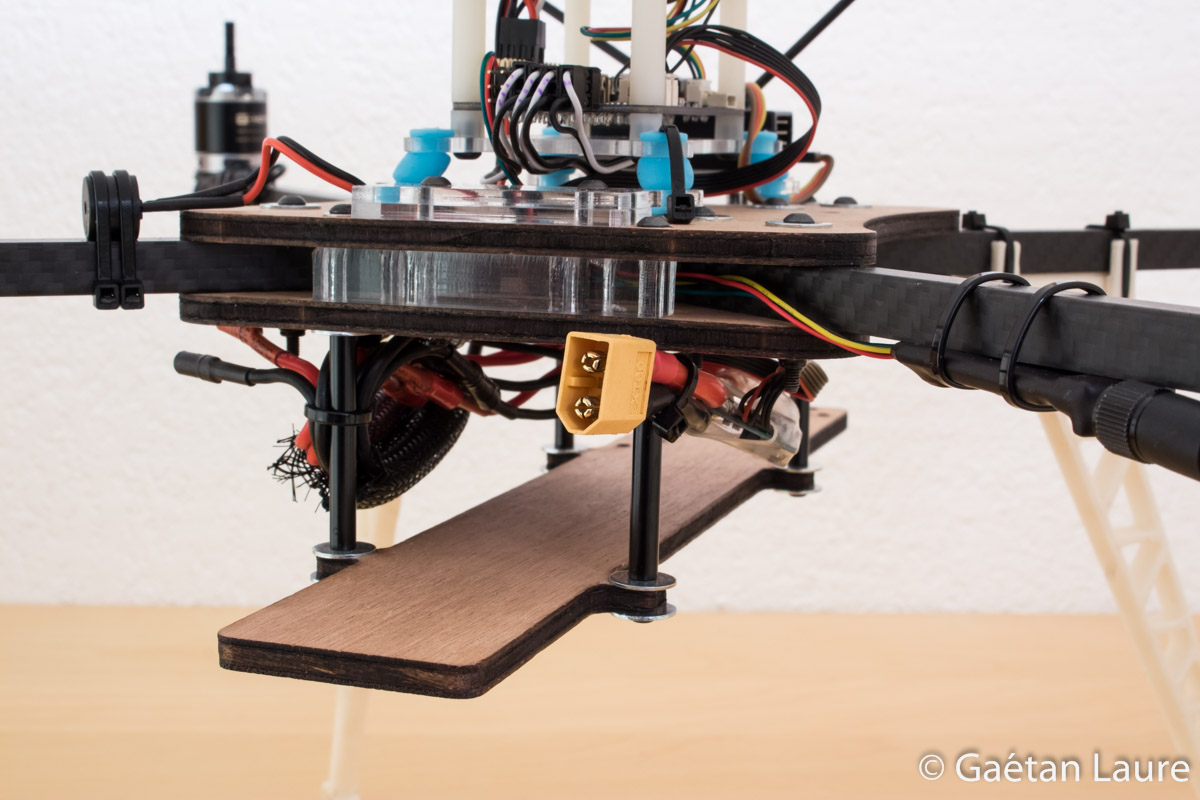
Let's now mount the battery tray.
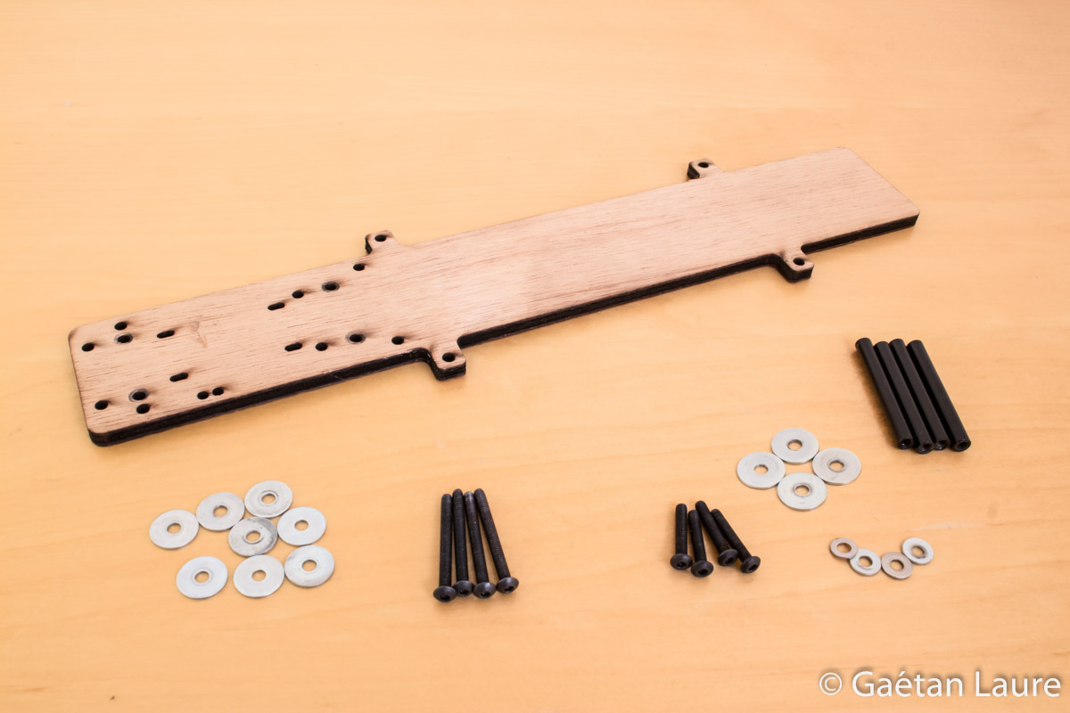
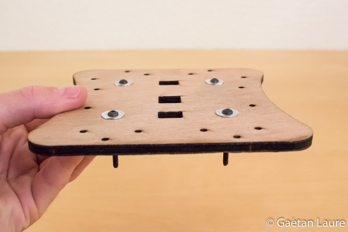
The battery tray, also laser cut into plywood. Four M3 40mm standoffs, M3 30mm screws and M3 18mm screws are needed to mount it on the frame.
Mounting the standoffs. I put threadlocker on the screws to avoid unscrew due to vibration.
The battery tray, mounted on the frame.
We can now mount the radio receiver and the buzzer.
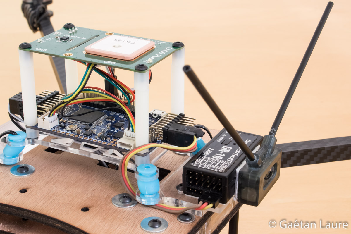
The radio receiver is attached on the vibration damping mount using double-sided tape. The two radio receiver antennas are fitted into plastic tubes, oriented at 90 degrees to each other (to improve the received signal quality). I use the PPM (Pulse Position Modulation) output of the radio receiver, thus all the radio channels are transmitted through only one wire. I connect it to the RC input 1 of the APM board. A jumper is connected to the signal pins of the RC inputs 2 and 3 to enable the PPM mode on RC input 1.
The buzzer is mounted on the left back arm using zip-ties. It's connected on the APM analog output A5.
Let's now mount the landing gear.
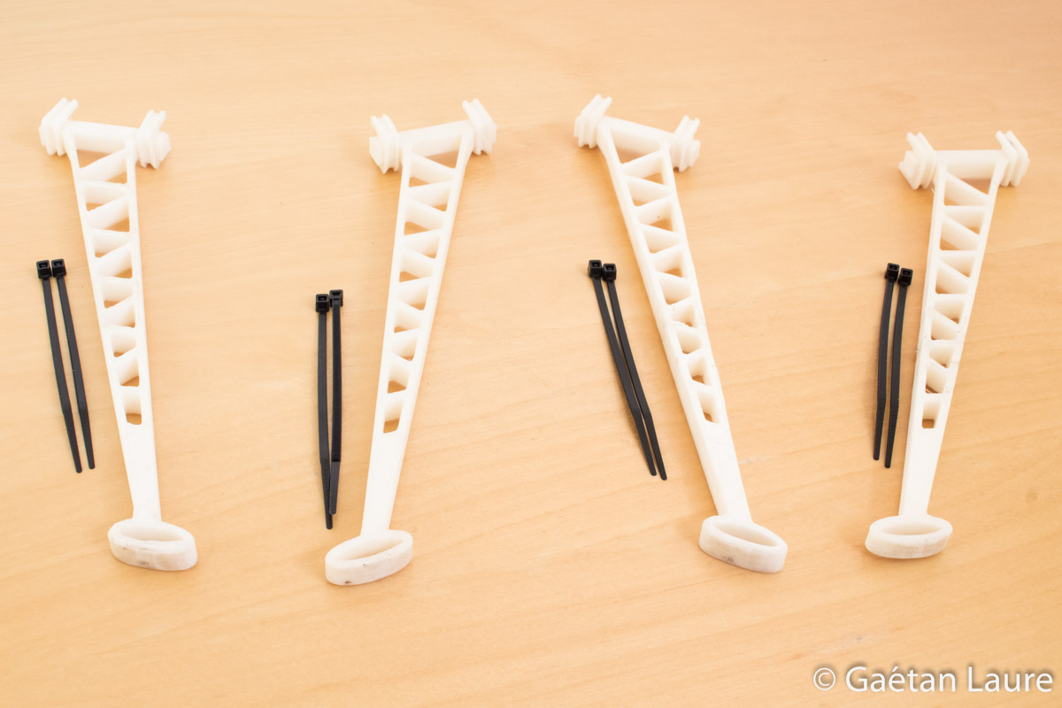
It's 3D printed using ABS wire to make it enough strong and resistant.

The landing gear is attached on the arms using zip-ties.
We can now install the telemetry module.
It's mounted on the right back arm using zip-ties.
I connect it to the telemetry port on the APM board.
It's time to install the power module and connect the ESC power wires.
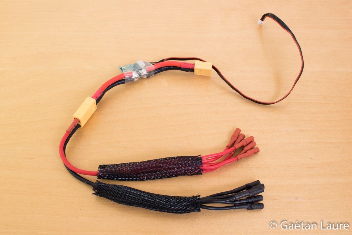
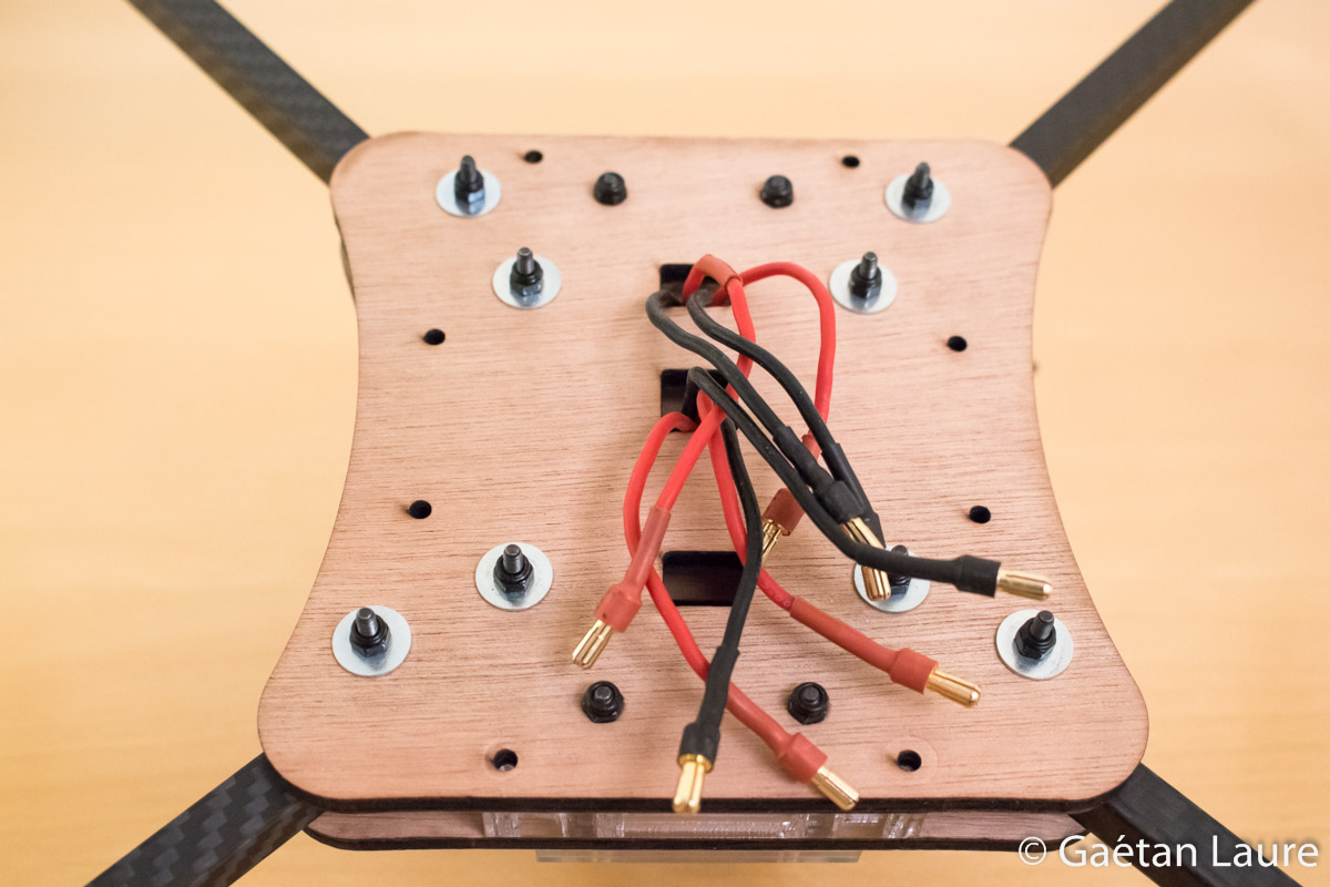
I connect the power module to a distribution harness from Hobbyking.
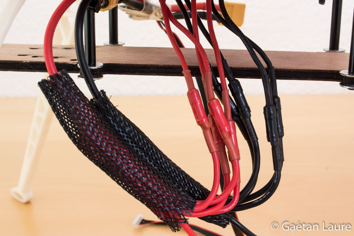
The ESC power wire are connected to the distribution harness. I use electrical tape to secure the connection of each ESC.
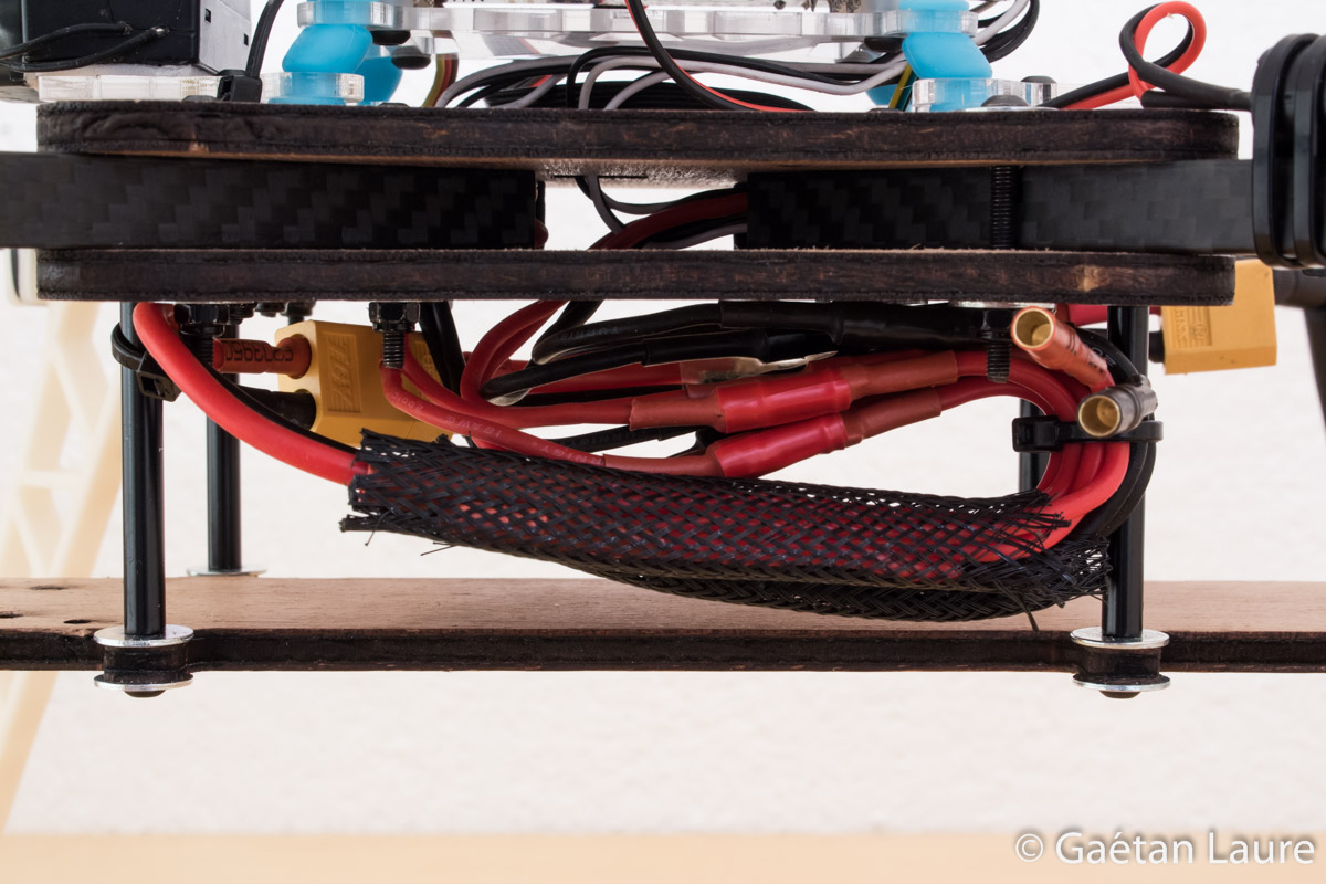
The distribution harness is attached to the battery tray standoffs using zip-ties.
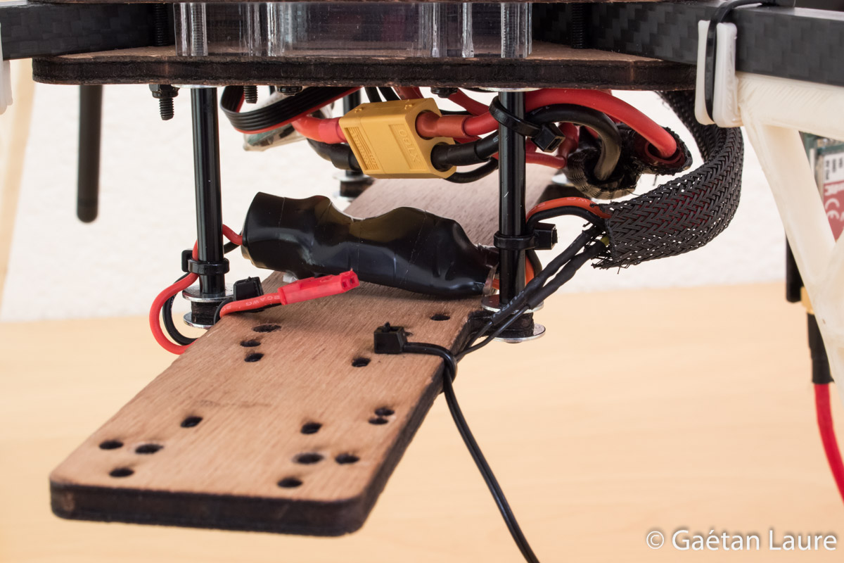
The power module is installed this way. The cable to power the APM board pass through the back holes of both plates.
It's connected to the APM power port.
The battery XT-60 connector located on the back side will facilitate the battery connection.
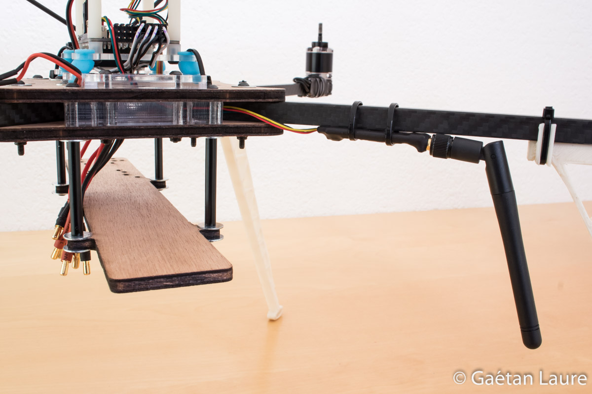
It's time to mount the video transmitter and corresponding wires.
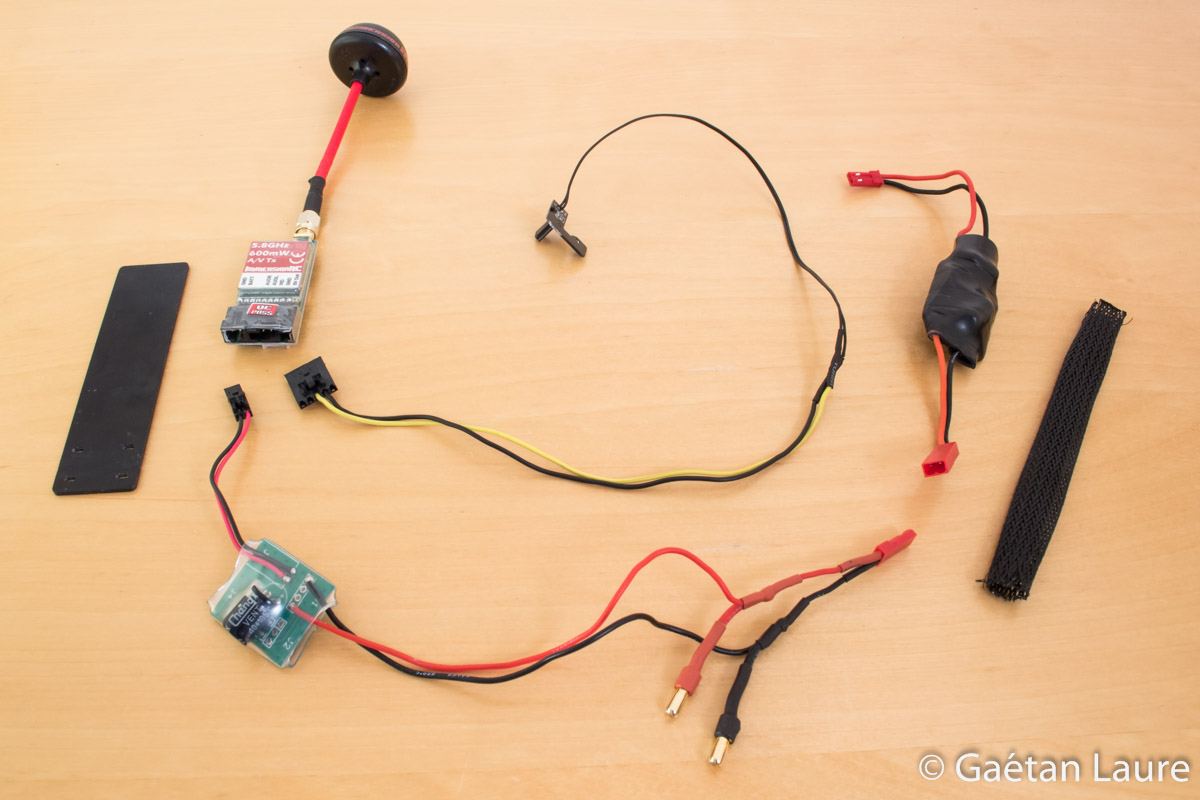
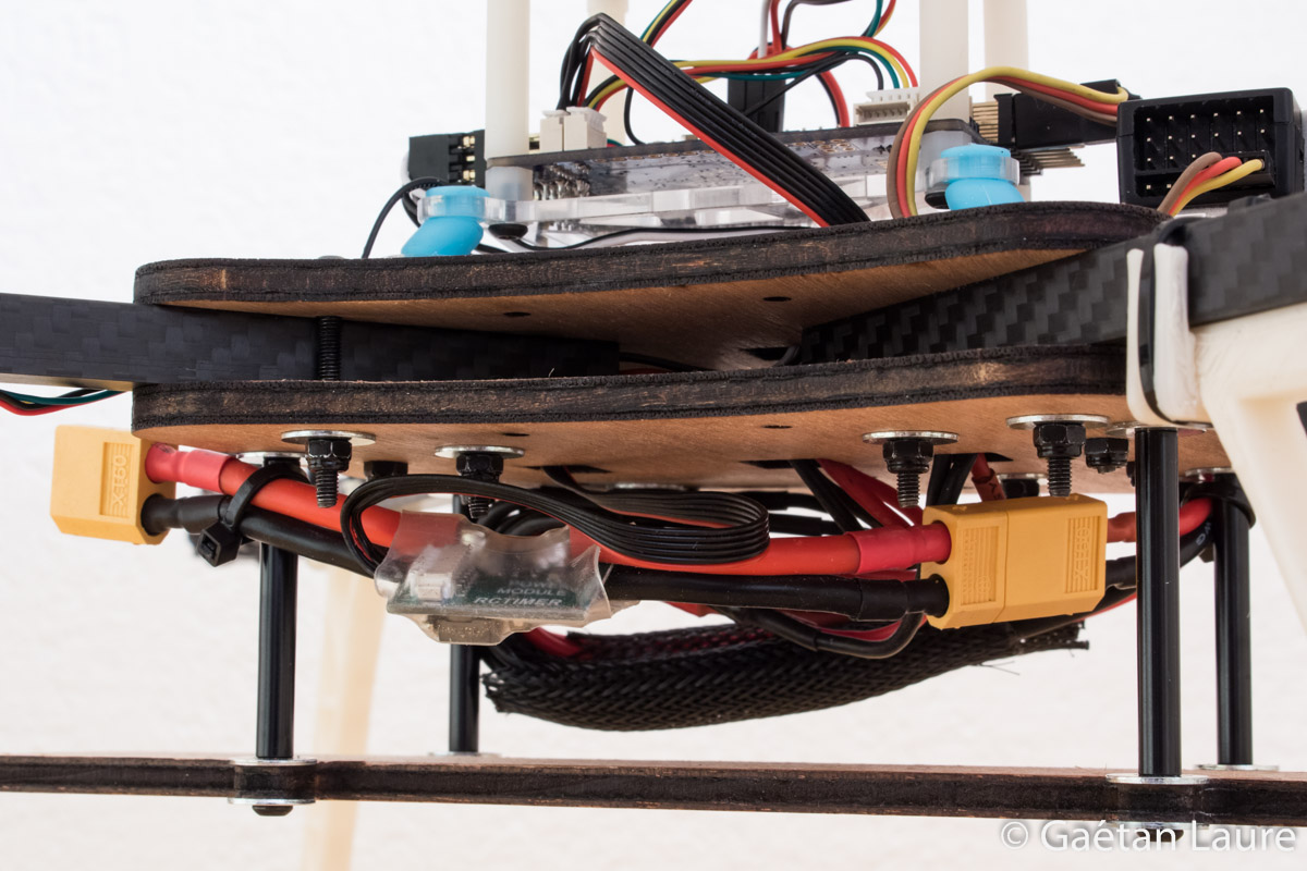
The ImmersionRC transmitter used is going to be mounted using the FPV transmitter post (on the left). The wire to connect the GoPro to the transmitter (which is a Tarot Gopro Hero3 AV Cable adapted to be plugged into the transmitter) is 38 cm long. The power wires are designed to connect both the FPV transmitter and the gimbal to the distribution harness (there are 18 cm between the LC filter and the JST connector, and 7 cm between the bullet connector and the JST connector). The LC filter (on the bottom left of the image) is used to smooth the battery power supply and avoid interferences on the video signal. A 12V regulator (on the upper right corner of the image) is used to adapt the voltage from the battery to the gimbal. I soldered wires with JST connectors on it.

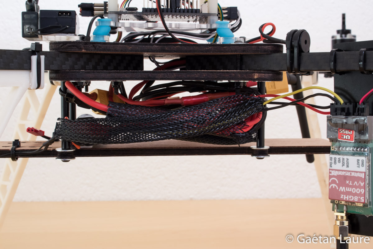
The transmitter is attached on the transmitter post using double-sided tape. The transmitter post is mounted on the left back arm using zip-ties. The power wires are connected to the distribution harness. All the wires are protected using 6mm wire mesh (12 cm long).
The 12V regulator is attached on the battery tray using double-sided tape. The wires are set this way using zip-ties.
We can now mount the gimbal and the GoPro.

The DYS smart3 and the GoPro 3. I 3D printed the yellow part, designed by Lasersaber, to mount the GoPro on the gimbal faster and without any screws. I always use a filters with the GoPro: the polarizing filter to reduce light reflections and protect the GoPro lens; or a neutral density filter (ND4) to slow down the GoPro shutter speed and avoid Jello effect in case of a bright daylight.
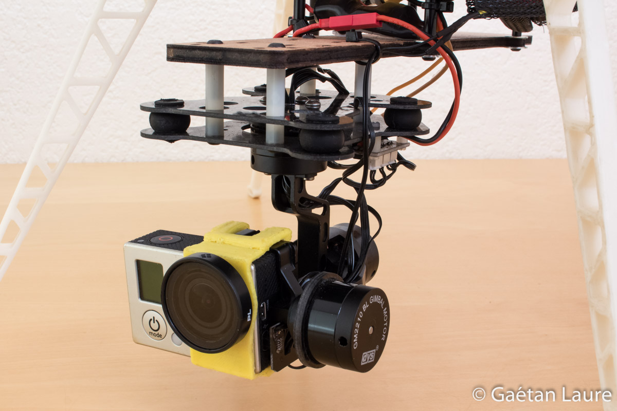
The gimbal is mounted using four M3 25mm standoffs and four M3 18mm screws. The GoPro is well maintained by the yellow mount. The hole of the yellow mount has been widened a bit to fit the filter inside. The gimbal power wires are connected to the 12V regulator output (through the JST connector). The video cable is connected to the GoPro mini USB port.

The video feedback wire pass behind the GoPro, it doesn't prevent the gimbal to move in any direction.

In order to control the gimbal orientation (around the pitch axis) from the radio, a signal wire (in orange) is connected to the RX-P input of the gimbal.
Pitch orientation will be sent through the APM board. The signal cable is connected to the A10 output.
Almost finished, let's now cover the barometer on the APM board (to avoid disturbed pressure measurement in case of wind).
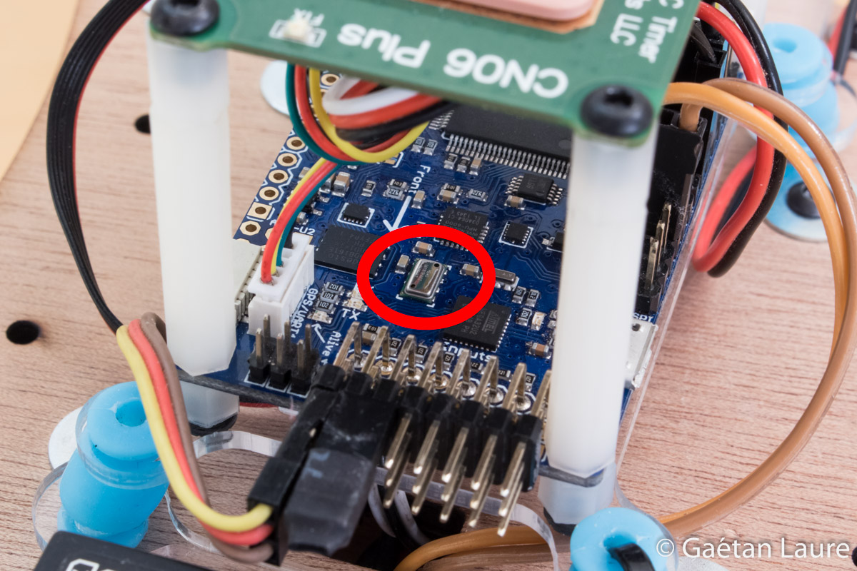
The barometric pressure sensor.
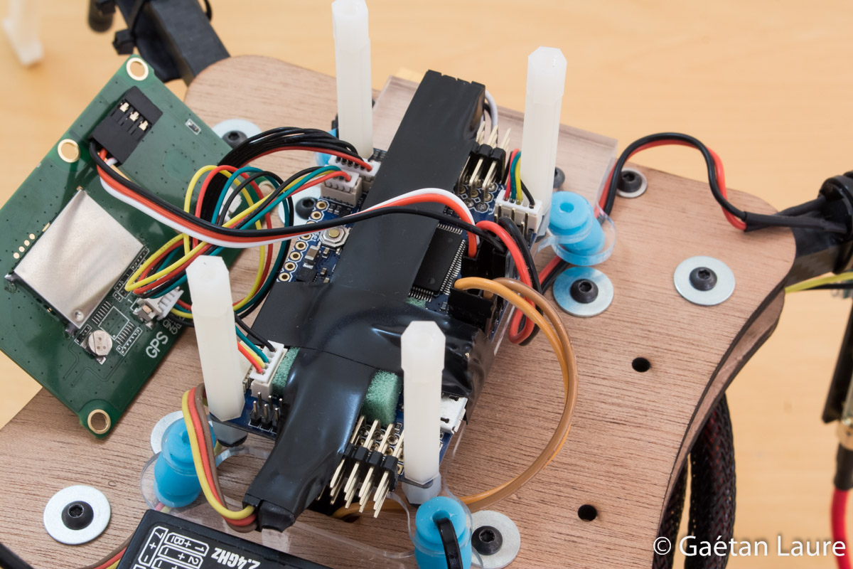
Covering it with some foam and tape. The tape also secure receiver and ESC wire connections on the APM board.
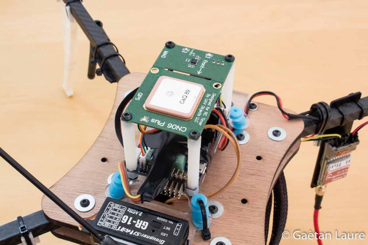
The GPS board reinstalled.
The only thing left is to mount the battery and the props.
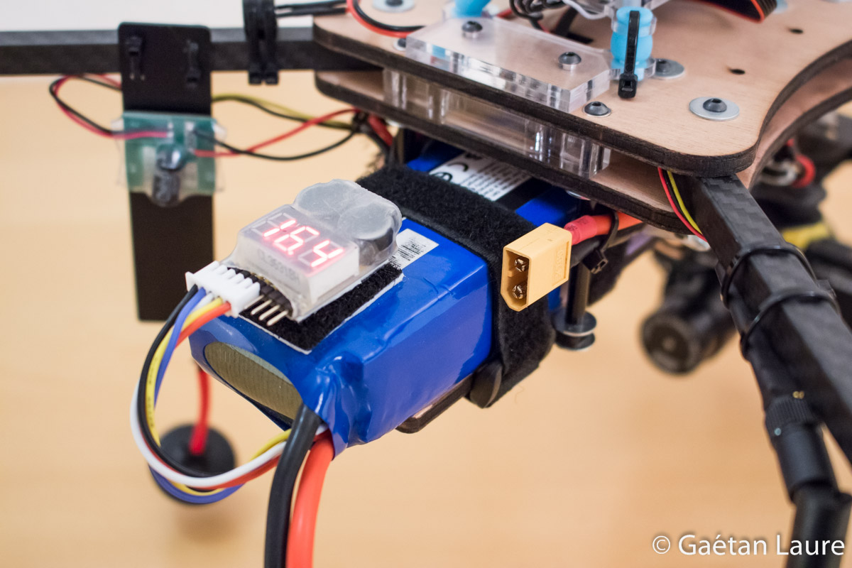
I use two straps to mount the battery. The LiPo cell checker is installed over the battery using Velcro.
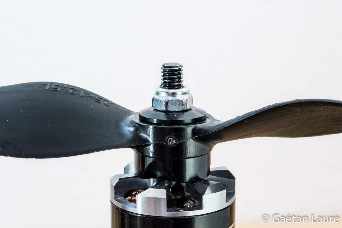
The props are held in place using M5 washers and lock nuts.
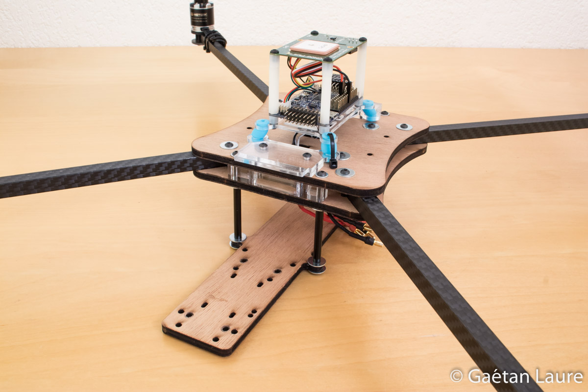
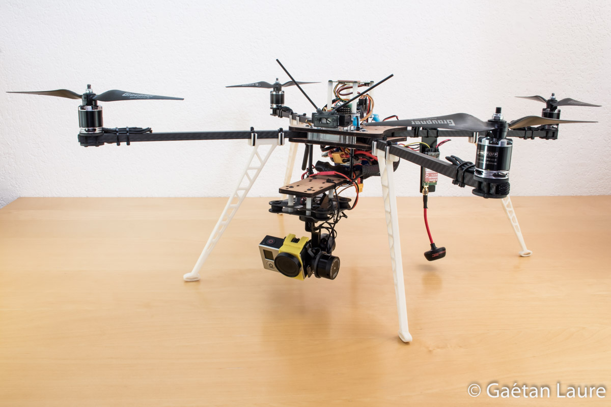
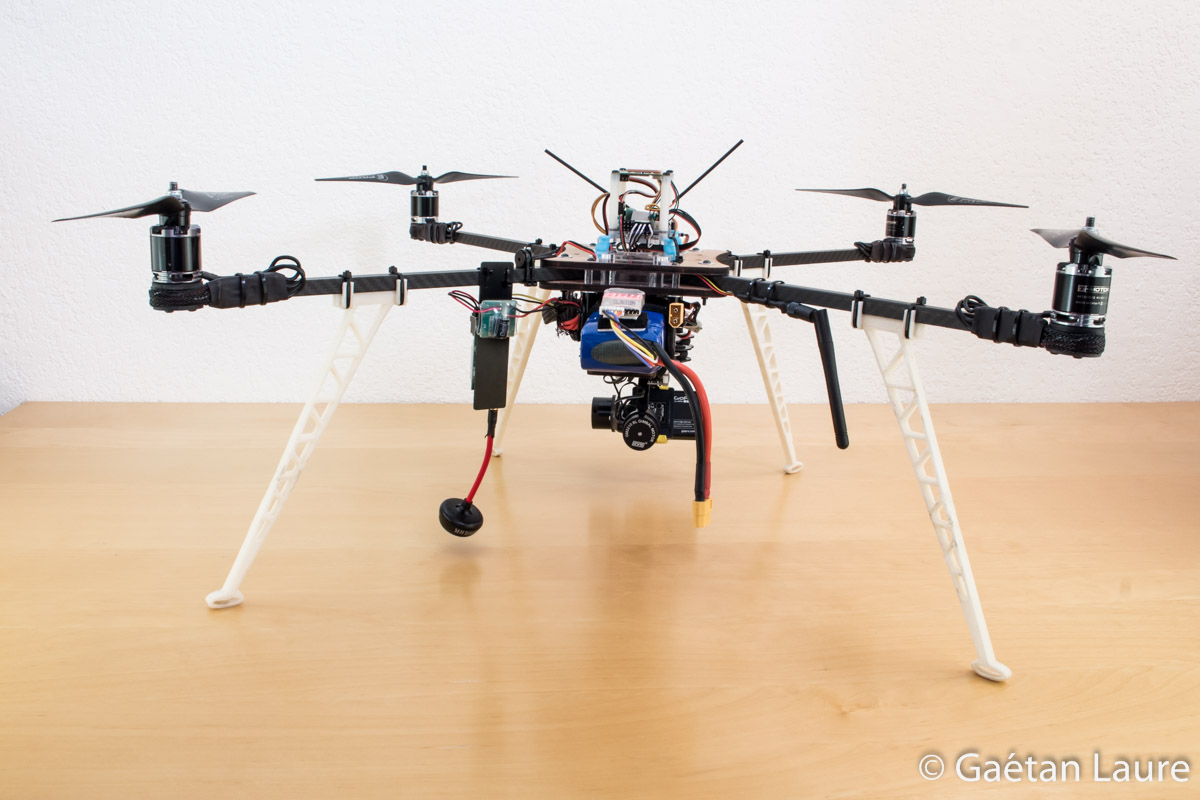
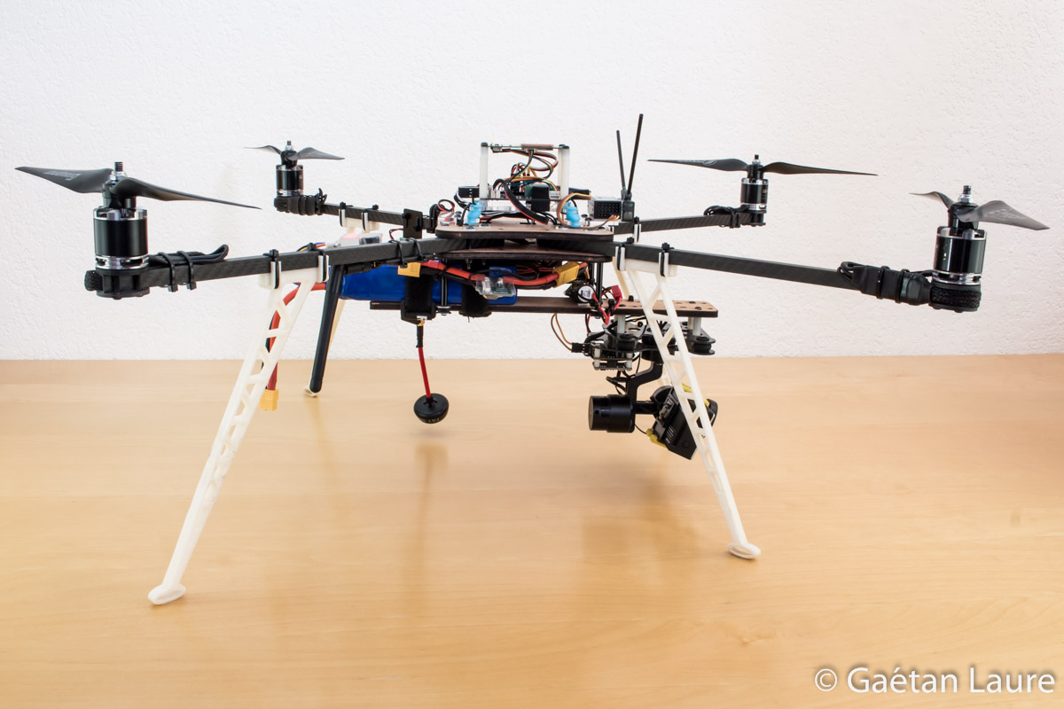
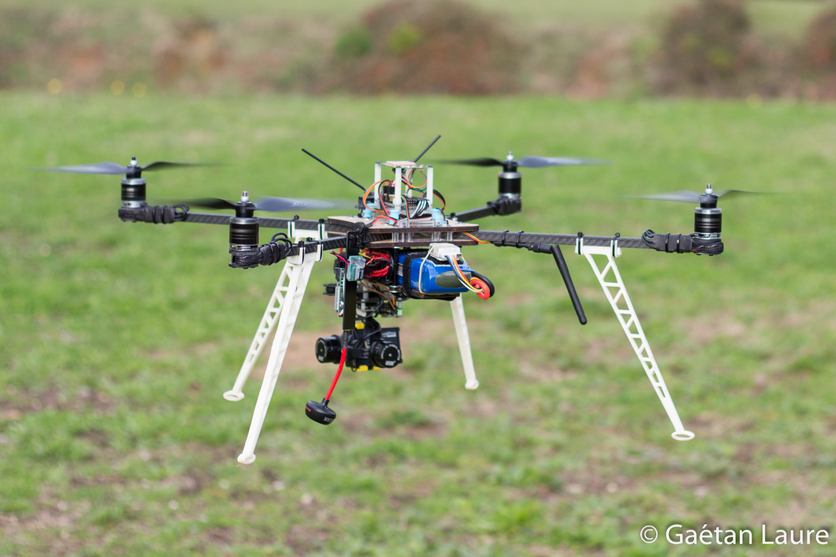
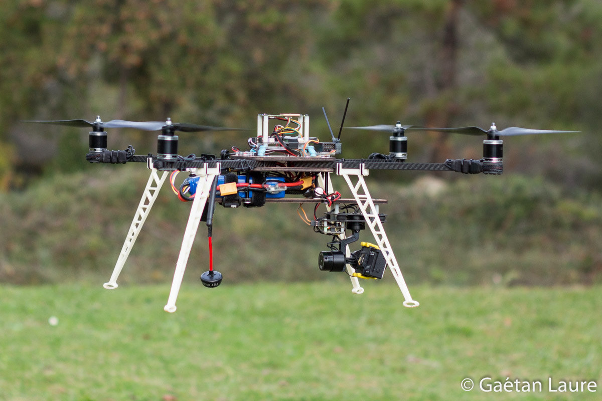
The quadcopter is finally fully mounted! Some pictures of the result:

ArduPilot configuration
It's now time to flash and configure the ArduPilot firmware on the APM 2.5. Everything is well detailed on the ArduCopter wiki.
I connect the APM 2.5 to a computer (with an USB cable) and use Mission Planner.

I first flash ArduCopter V3.2.1.
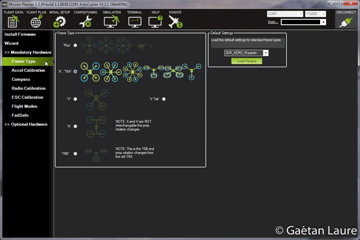
I can now set up the board (all the configuration procedure is described on the ArduCopter wiki). I first set the frame type as 'X'. After that, I perform the accelerometer calibration (it consists of placing the quadcopter on each edge to set default accelerometer min/max and offset on the 3 axis).
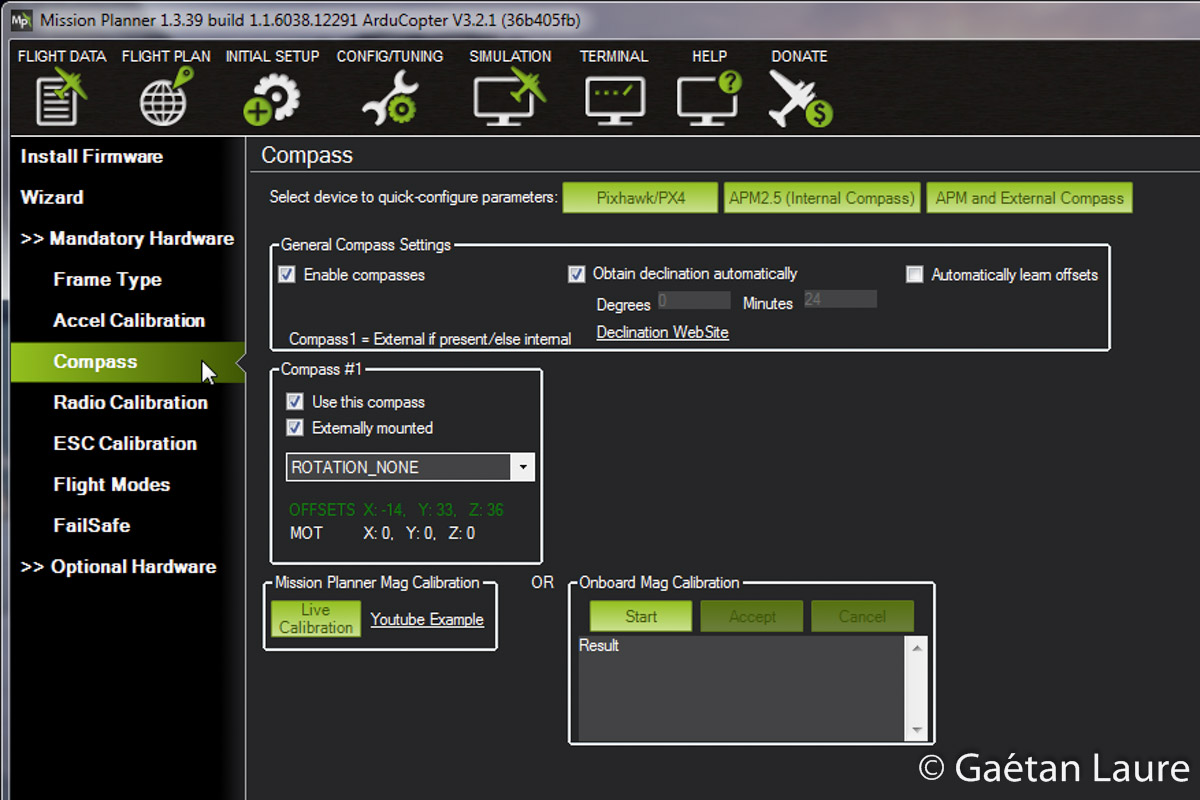
I now configure the compass. I use the external one (which is on the GPS board). The "live calibration" consist of rotating the quadcopter around all axis. After that, I perform the radio calibration. It consists of moving the radio sticks and switches to set their corresponding minimum and maximum values.
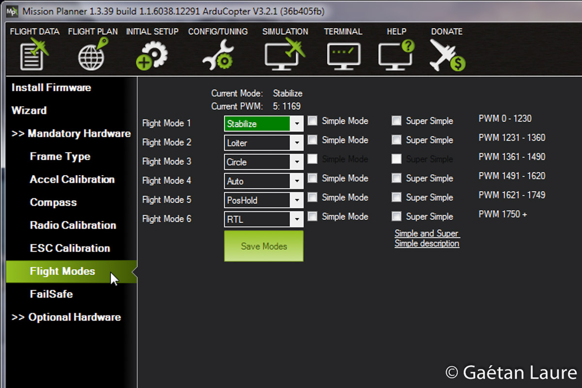
I then configure the flight modes used. All the modes are described in depth here. "Stabilize" is the basic flight mode, to fly manually, controlling the roll and pitch angles of the copter. When the sticks are released, the vehicle automatically levels itself. "Loiter" is a GPS assisted mode. Sticks control the copter relative motion.It makes possible to fly given a straight line. When the sticks are released the copter stops and holds its position and heading. "Circle" mode makes the drone describe a circle of a given radius at a given turn rate. A zero radius will cause the copter to stay in place and rotate, it's very useful to perform panorama. "Auto" mode is used to fly through pre-programmed waypoints. "RTL" ("Return To Launch") is used to make the drone fly back and land to the takeoff location.
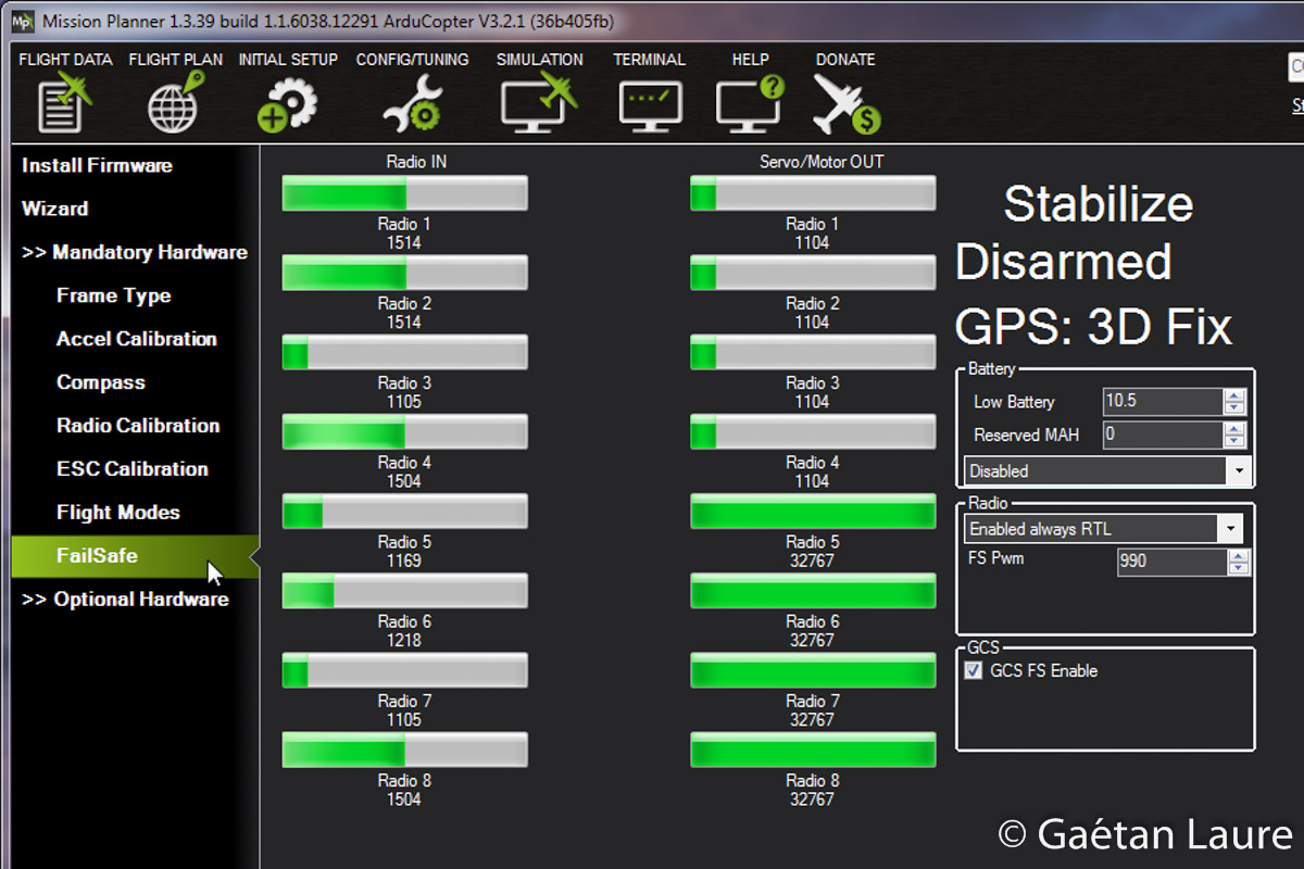
I now set up the radio failsafe, it will ensure the drone comes back home automatically in case of signal lost. The receiver has been configured to pull the throttle channel to 900 in case of signal lost. I set "FS PWM" to 990: when the throttle channel is below this value, the failsafe procedure (a "Return To Launch") is engaged.
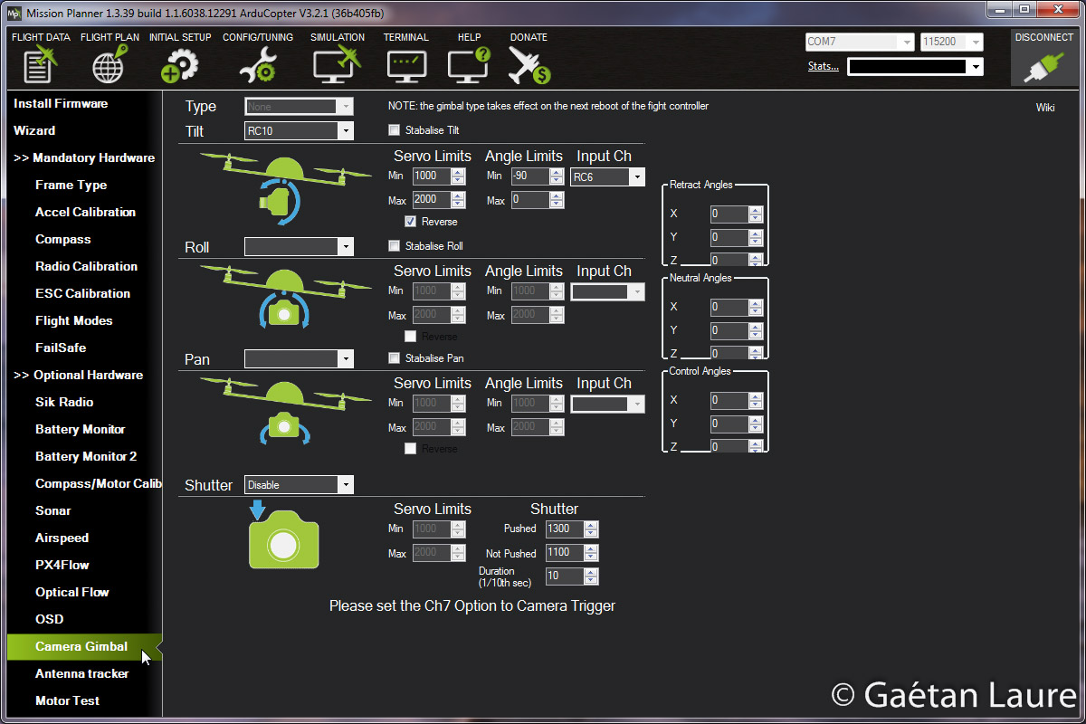
The gimbal is configured this way. I can control the tilt angle through the APM. I'm doing it using the RC6 channel input and the RC10 APM output.

Here is how I configured the PID gains. I first used the "AutoTune" mode to make the quadcopter configure the gains by itself. I then adjusted the values to get a better compromise between a smooth and quick response, to get a steady video (avoiding oscillations) and manage correctly external perturbations (such as wind..).
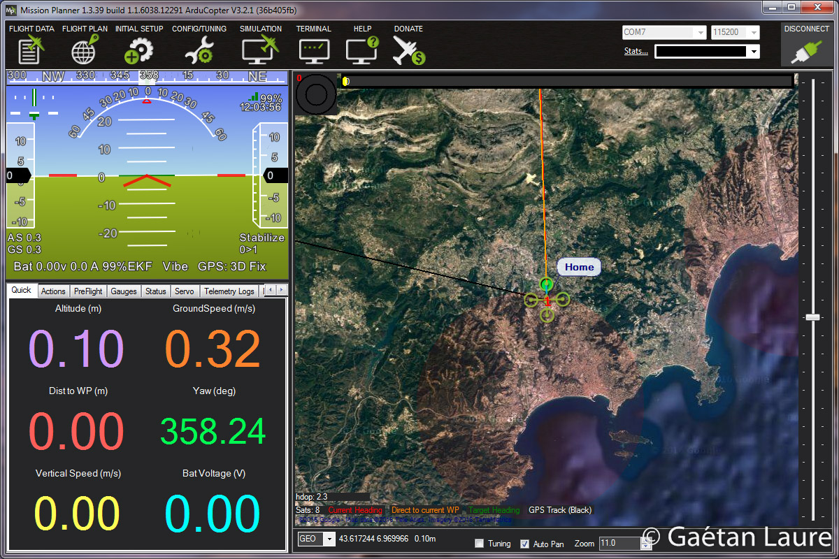
Once the configuration is done, we are ready to fly. We can use Mission Planner as a ground station, with the telemetry modules, to get live quadcopter information. We can also use a smartphone with the app DroidPlanner 2 (or Tower) as a ground station.
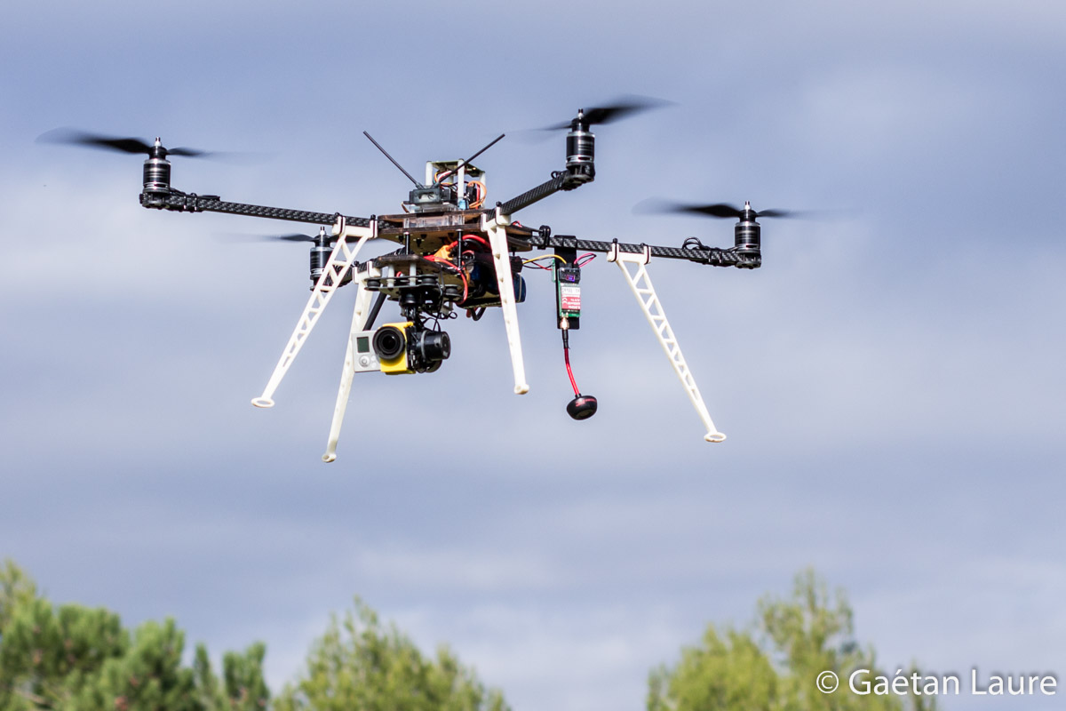
The quadcopter flying
It's now time to fly!
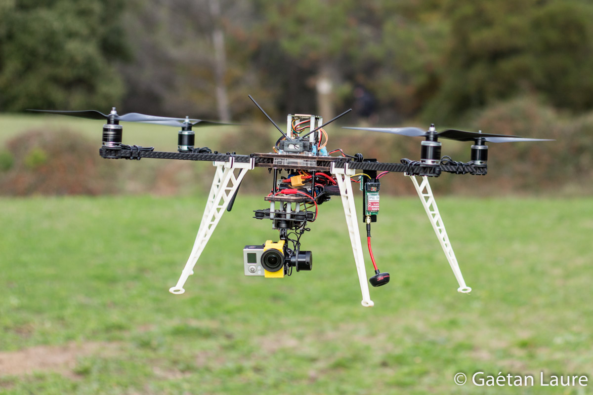
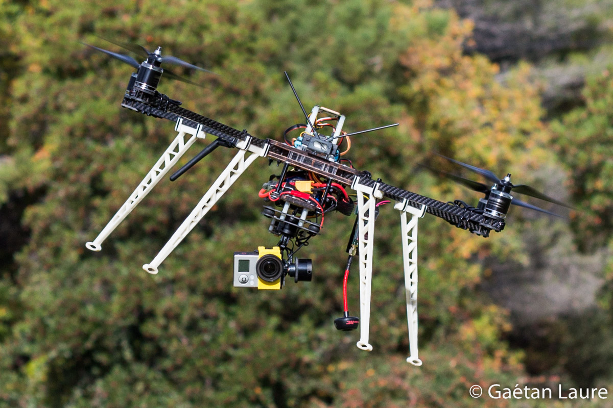
The GoPro stays horizontal when the quadcopter is tilting, thanks to the gimbal.
Some in-flight videos:
hi i wanted to build this drone and i was wondering how much this drone cost for all of the parts?
Hi,
For the drone itself it’s about 750 € (including the gimbal, the video transmitter, the SpiroNET antennas, the 433MHz telemetry and two LiPo batteries). You can reduce the price to about 600 € using the T-Motor Air Gear 350 pack (which seems quite good).
After that, you have to add the GoPro (3/3+ or 4), the radio transmitter (I would recommend the Taranis X9D) and a video receiver (FatShark goggles or a classic FPV monitor screen).
Really nice. I appreciate all of the pictures and descriptions, especially of the systems wired together external of the frame to show how it all connects. I also appreciate that you are trying new things, (plywood components rather than carbon fiber). Hope that you continue improving your innovative design and post pictures. Regards.
Thanks for your comment! I’m glad if my pictures and wiring diagrams are useful 🙂
Sure I’m going to improve it!
Bonjour,
Sur base de quoi déterminez-vous les KV nécessaires, les hélices nécessaires et la batterie nécessaire?
J’utilise e-calc depuis un petit temps et je ne comprends pas très bien l’interdépendance entre toutes les variables…
êtes-vous partis de la masse totale du drone en premier lieu dans e-calc et de ses dimensions ? (~1700grammes)
Je construis un drone d’envergure 500mm, de masse 2500g et je recherche les KV, la batterie et les hélices.
L’état de l’art m’indique approximativement une 3S 5000mAh, 10×4,5 d’hélices et entre 800 et 1000KV.
Le problème est que entre 800 et 1000KV, il s’en passe des choses sur e-calc ! De plus, passer d’une batterie 3S à 4S augmente l’autonomie et le rapport Poussée/Masse mais augmente l’énergie électrique nécessaire.
J’ai vraiment beaucoup de mal à trouver le juste milieu.
D’avance merci pour votre aide,
Bien à vous.