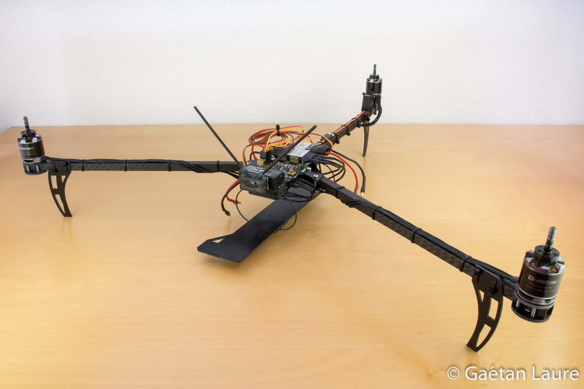
In this post I'm fully describing how I built my second version of the tricopter, starting from the RCExplorer Tricopter V3 kit.
This tricopter is an upgrade of the previously built Tricopter V1, I'm using the same electronic components. I built this new version to get more performance in term of flight time and stability. Using carbon fiber arms enable to get a lighter drone and improve its resistance to crash.
Setup specifications:
- Frame: David Windestål's Tricopter V3 kit
- Arms: Square carbon booms (10x10x325 mm)
- Flight Controller: Quanton rev. 1 board (similar to OpenPilot Revolution board)
- Motors: T-Motor MT2216-12 V2 800KV
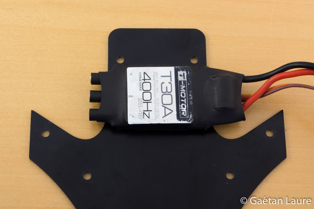
- Brushless Controllers (ESCs): T-Motor T30A
- Props: APC Slow Fly 10x4.7"
- Servo motor (for the yaw axis control): Turnigy TGY-210DMH
- Battery: Zippy 4S 3000mAh 20C
- Radio Controller: Graupner MX16 Hott and GR-16 receiver
- FPV equipment: FatShark Attitude V2 goggles / 5.8 GHz FatShark video transmitter / 600TVL FatShark camera
- Additional camera: GoPro Hero 3 Black
- All up weight: 1160 grams (including battery and GoPro camera)
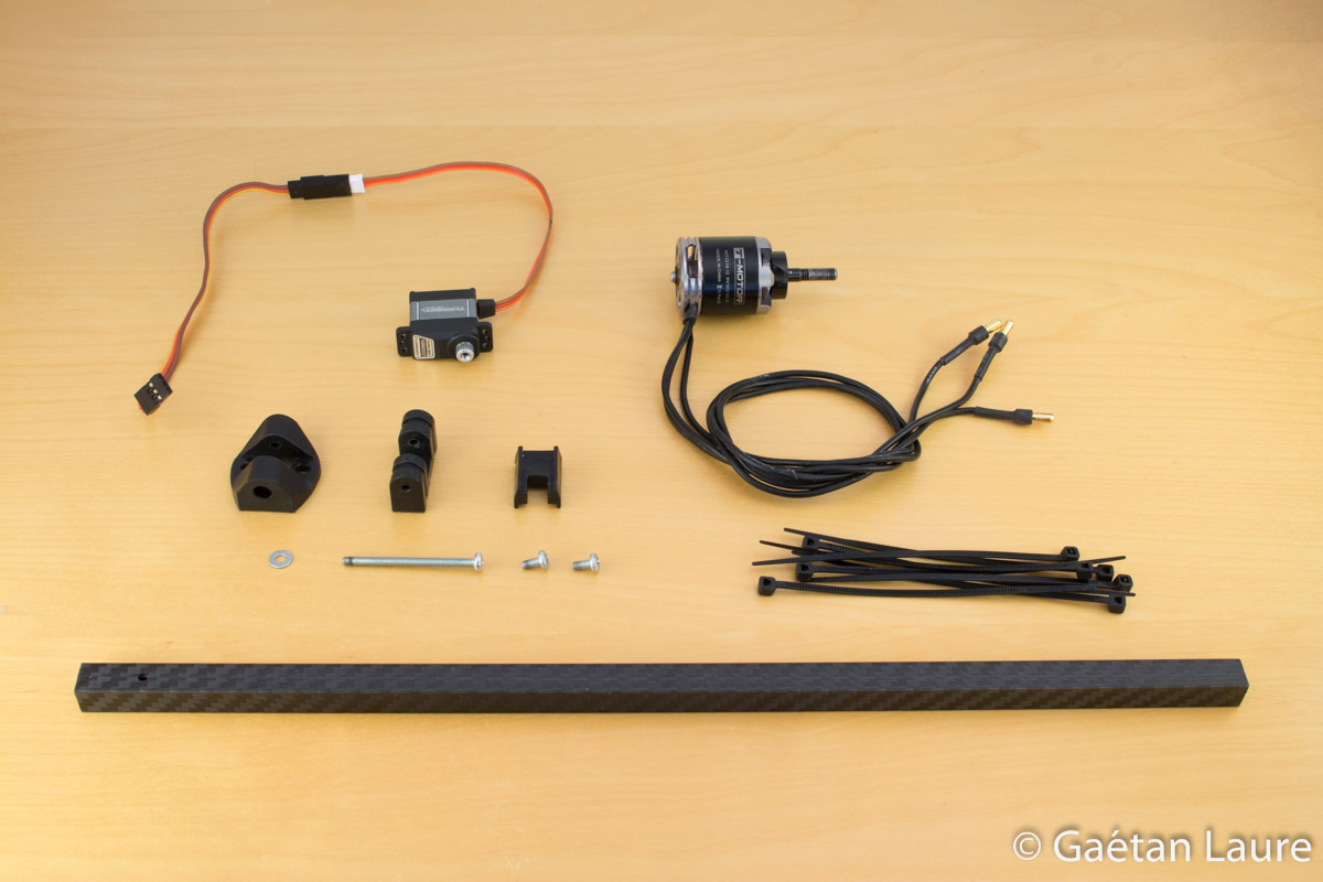
Before starting the building, let's rapidly show the different equipment used:
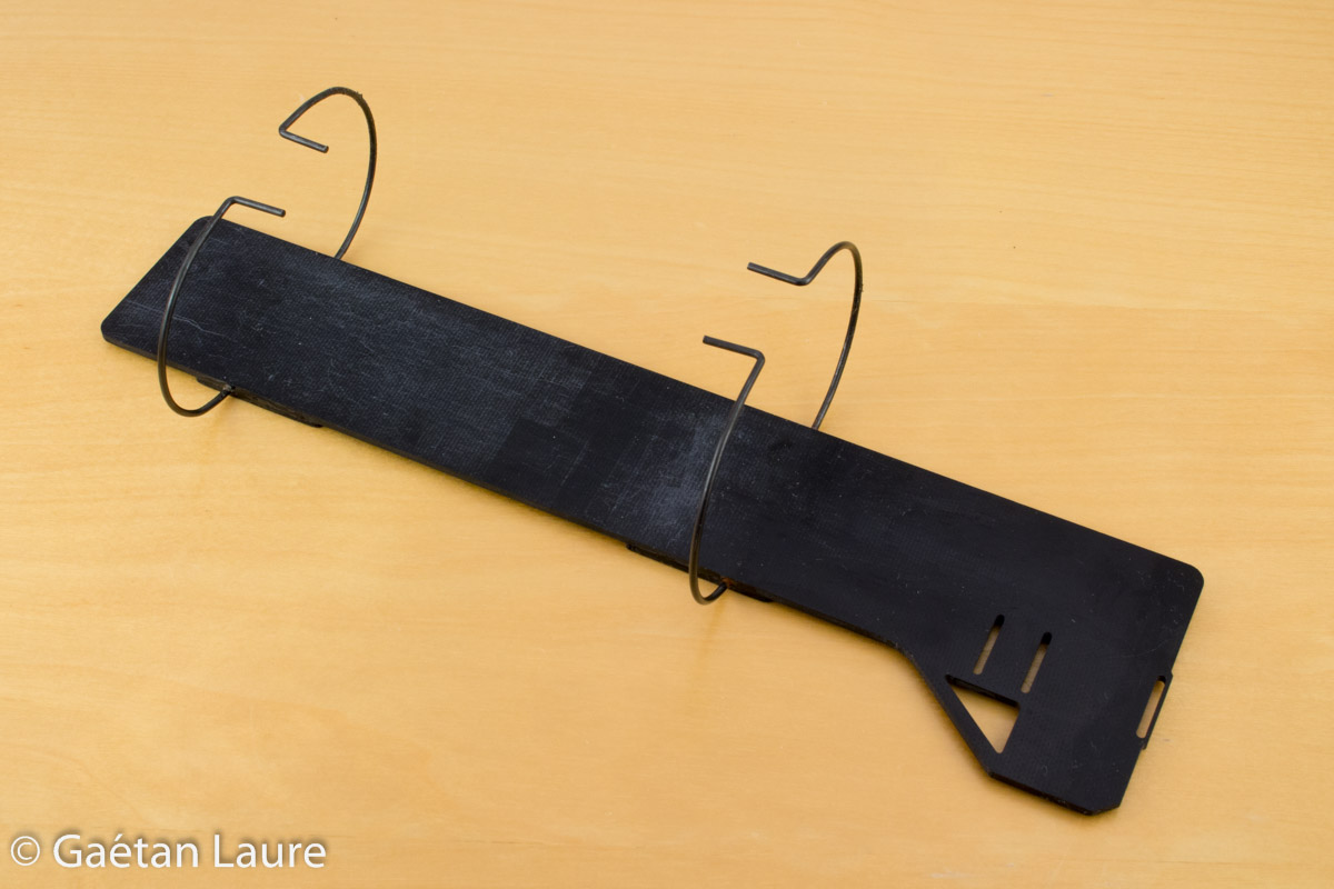
For the mechanic part, I use this frame kit available on RCExplorer store:
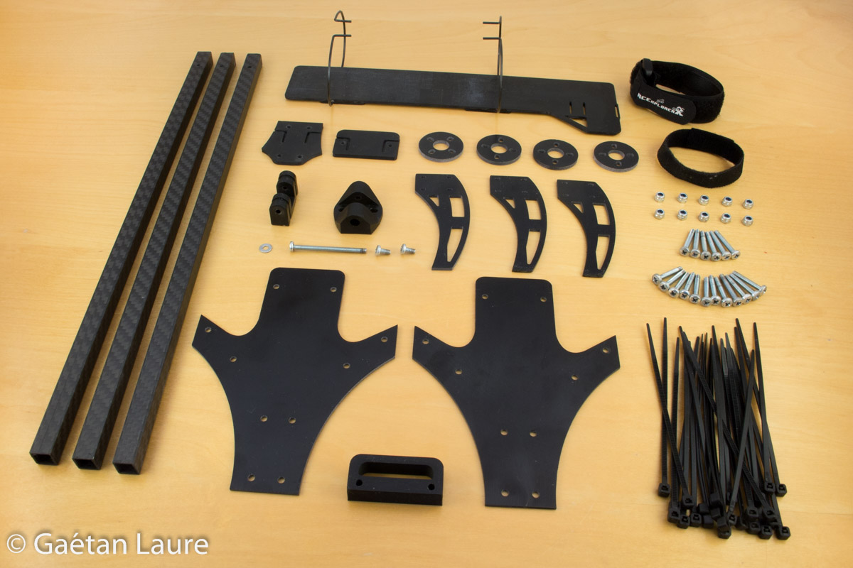
Pieces seem a bit used because I actually used them before writing this article and taking pictures of the build.
Concerning electronic, I'm using the same components than the Tricopter V1.
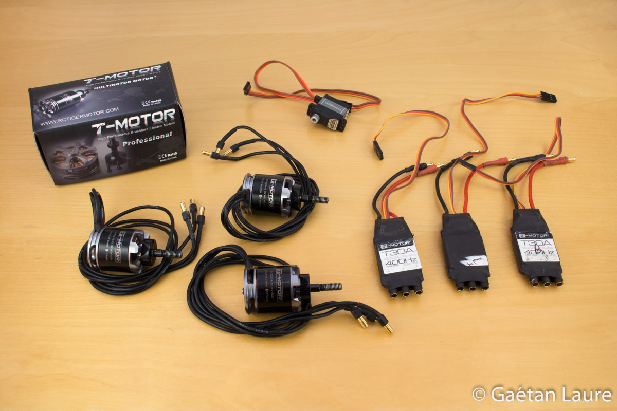
Motors and ESCs are T-Motor ones (T-Motor MT2216-12 V2 800KV and T-Motor T30A) and the servo motor used to control the yaw axis is a Turnigy TGY-210DMH from Hobbyking.
To power the drone, I use a Zippy 4S 3000mAh LiPo battery (14.8 V nominal voltage).
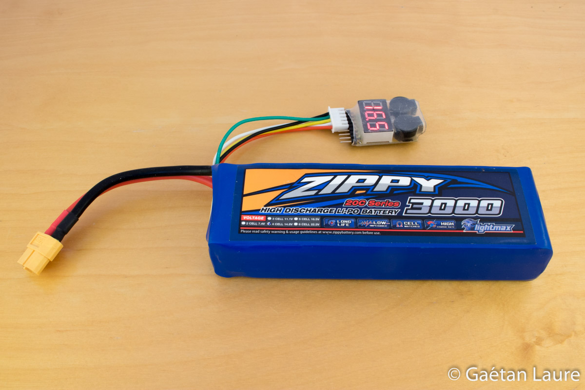
To ensure the battery safety during flights, I use a LiPo cell checker, that is constantly checking the voltage of each battery cells and buzz in case of a too low voltage (which can irreversibly damage the battery).
To control the drone, I use the Graupner MX16 Hott radio controller and a GR-16 receiver.
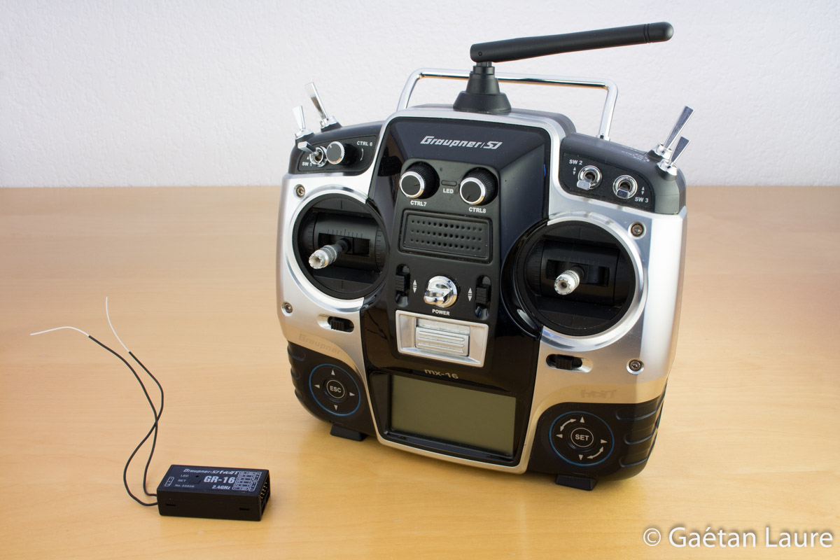
With such a radio controller, you can control the drone up to 2 km range (without obstacles).
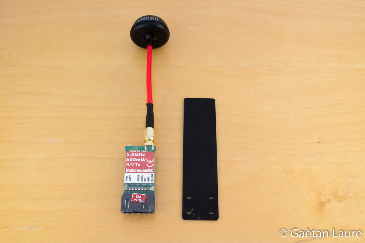
In order to get a first person view (FPV) video feedback, I'm using a FatShark 600TVL camera and an ImmersionRC 5.8 GHz video emitter (with a spiroNET antenna).

The video emitter is directly powered by the drone battery through a power filter (the little module on the left of the image) which is simply a RC noise filter circuit.
I receive the video signal through FatShark Attitude V2 goggles also equipped with a spiroNET antenna.
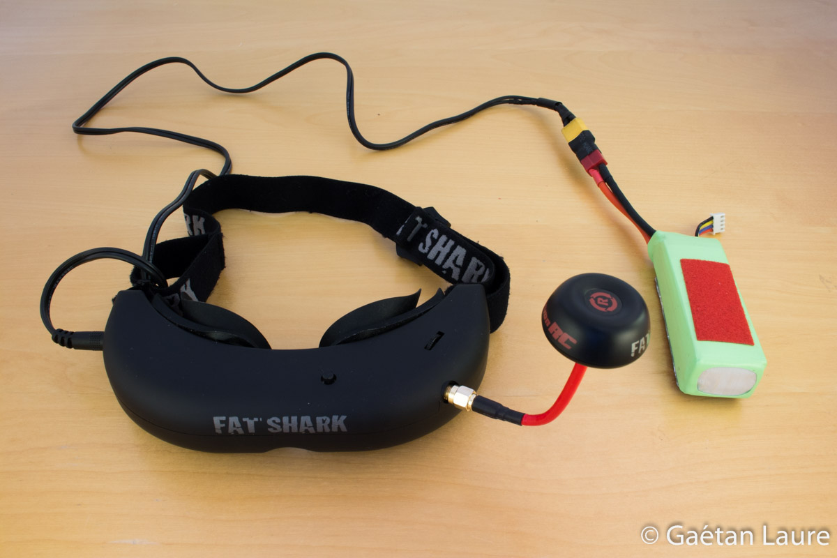
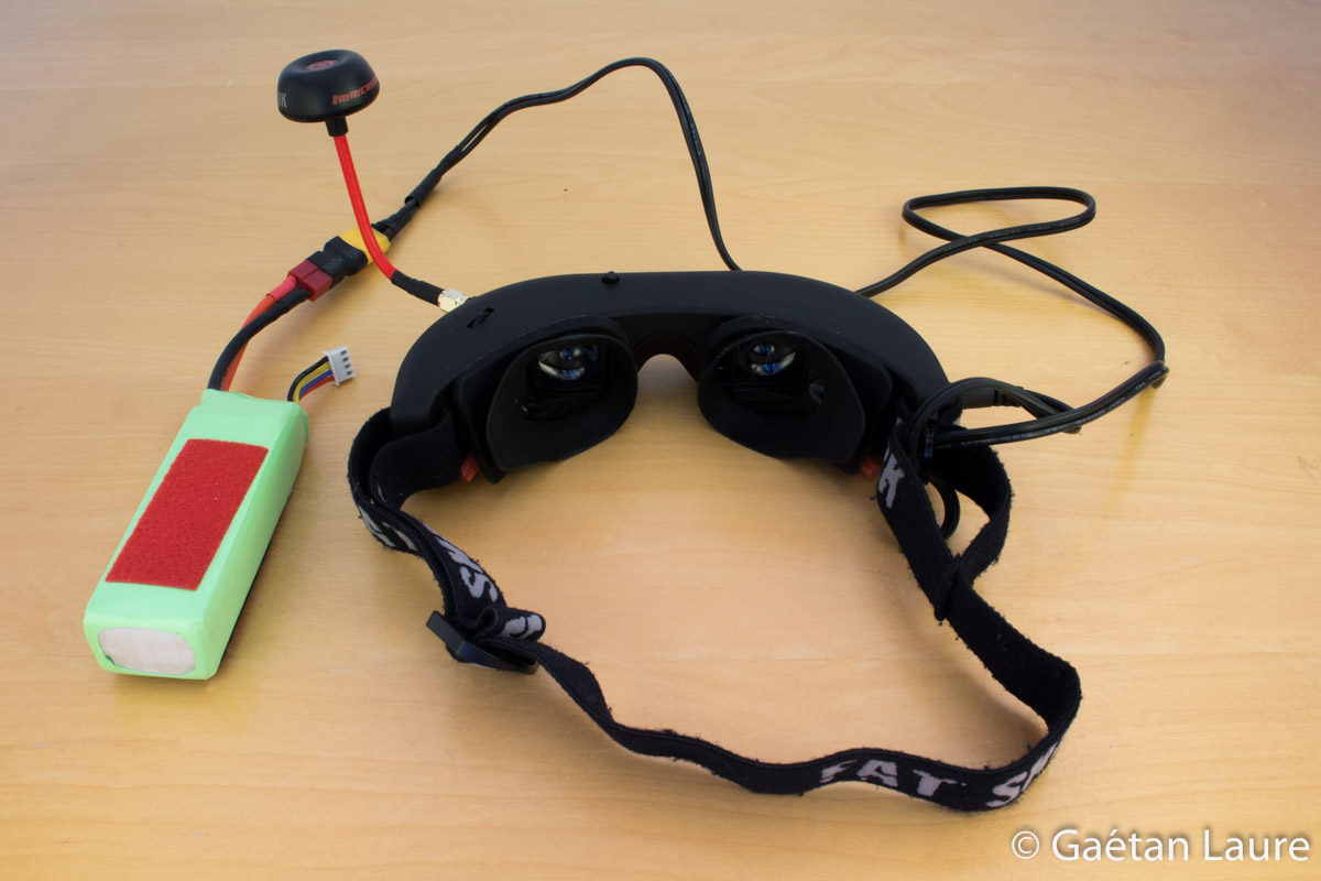
Goggles are powered using a 3S 2200 mAh LiPo battery.
With such a FPV system, the video signal can be received up to 1 km range (without obstacle).
Let's now build the tricopter!
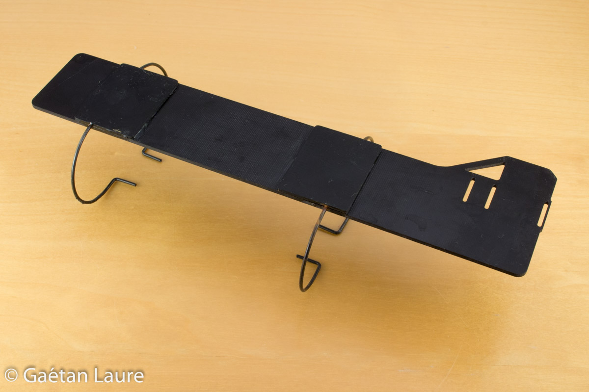
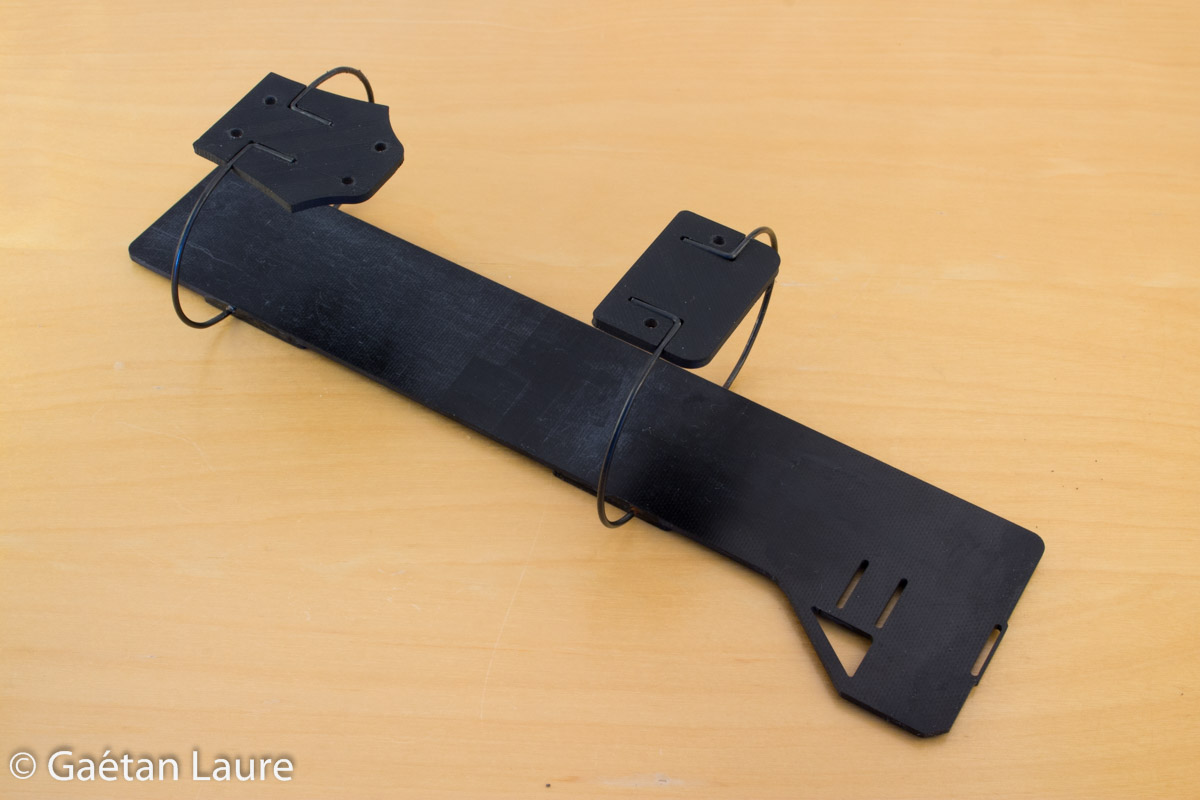
We begin with the battery tray which was already assembled (because I used it before writing this article).
The wire dampeners are fitted, using CA glue, to the bottom of the battery tray.
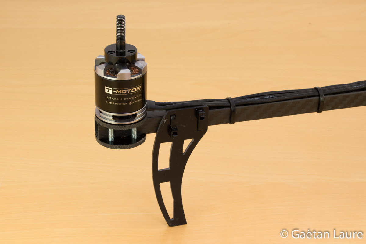
Let's now mount the front arms.
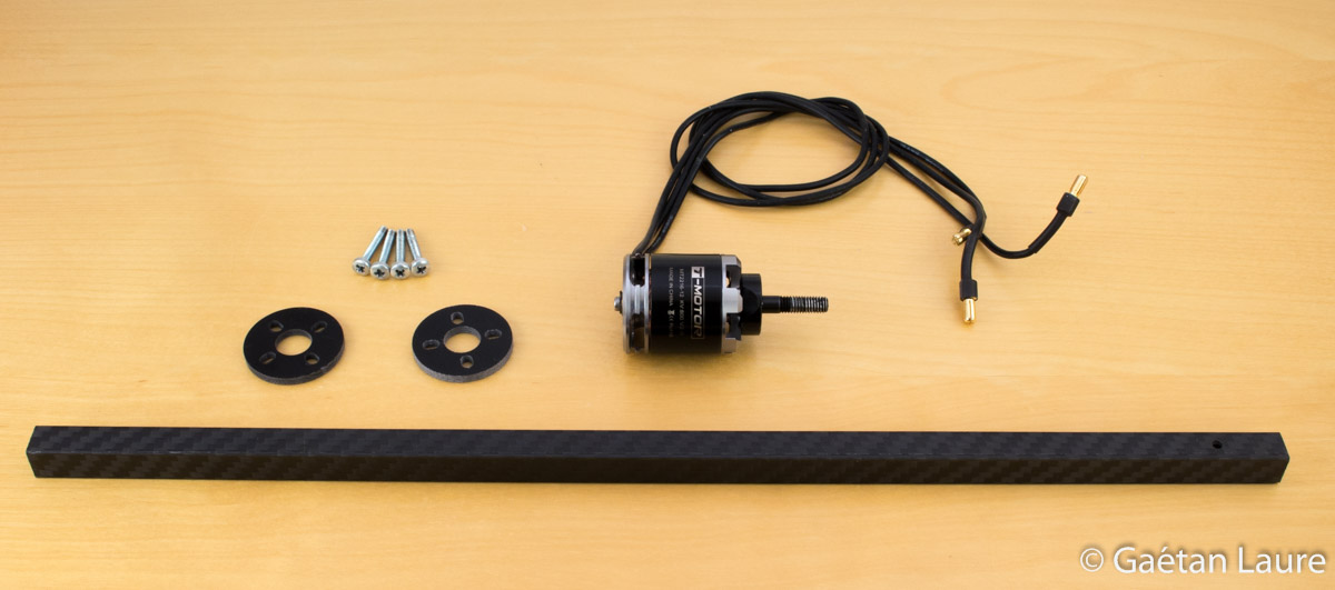
The motors are attached using circle motor mounts and screws.
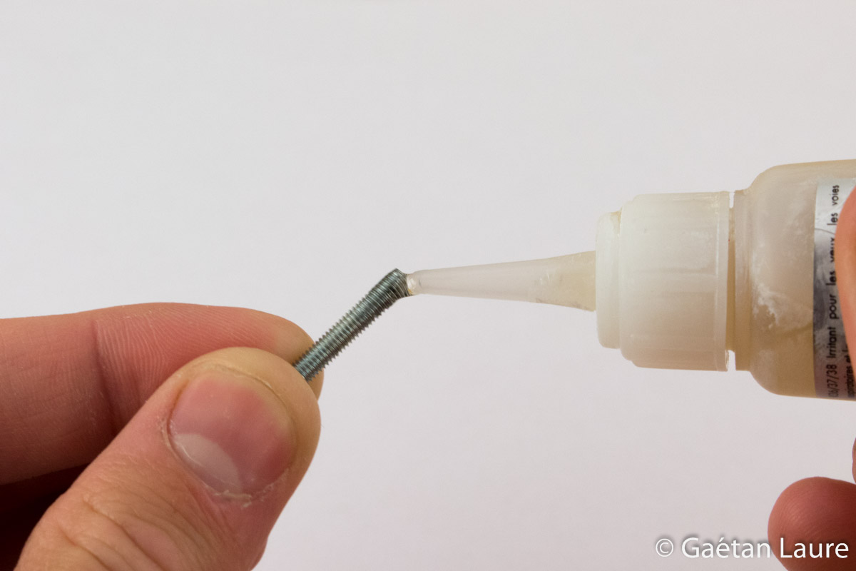
I always put threadlocker on the screws to avoid unscrew due to vibration.
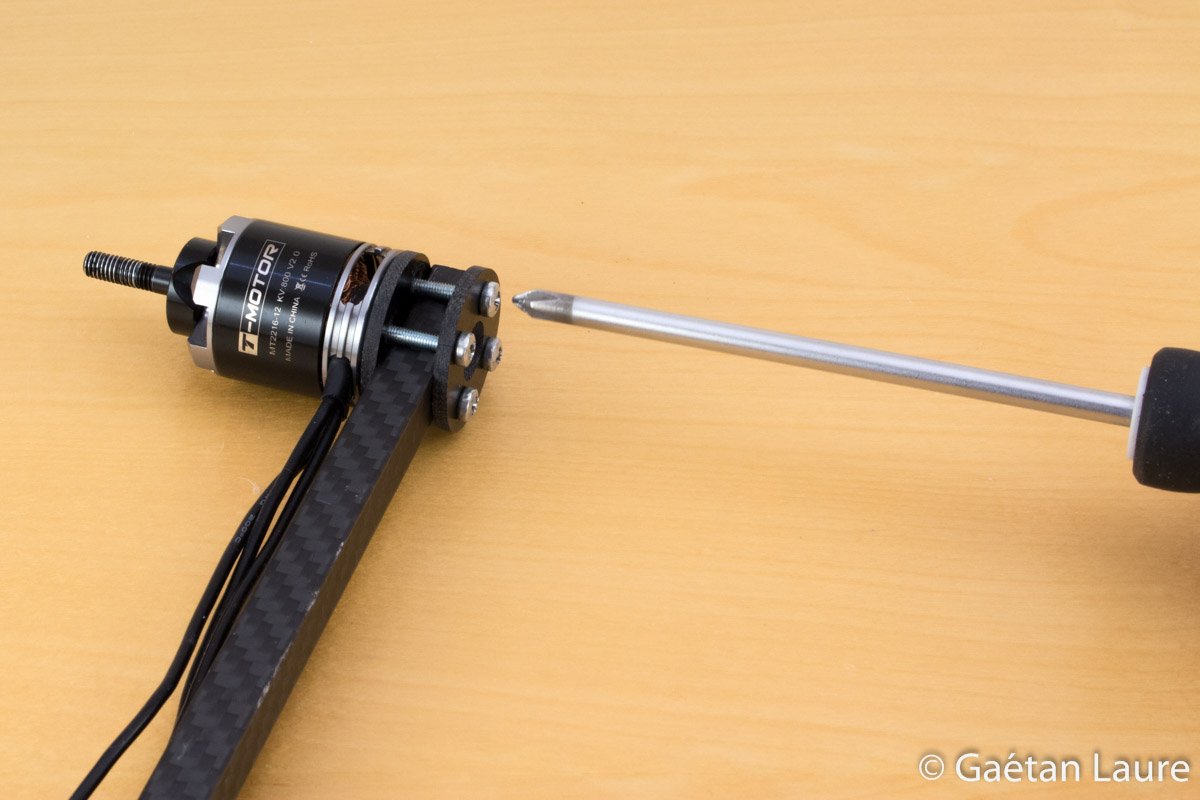
I screw a few turns at a time, describing a cross pattern, to get an equal tension on the four screws at the end.
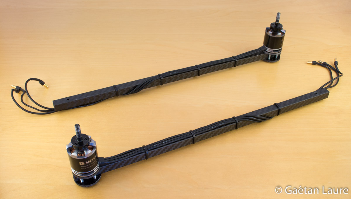
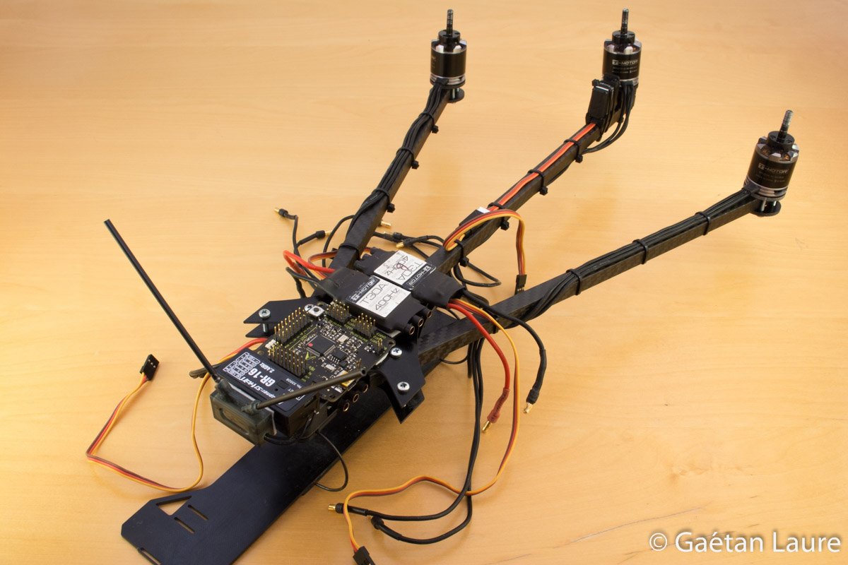
The motors are then mounted on the two front arms:
Let's now mount the back arm.
It's a bit more complicated because the back motor has to be tilted to control the yaw axis of the tricopter.
For that purpose, we use a "tilt mechanism".
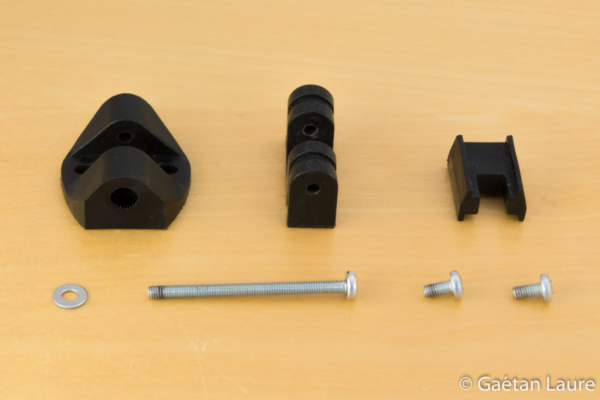
This one is injection moulded made from black fiberglass reinforced nylon parts. It fit perfectly the servo motor.

The servo motor used is a Turnigy TGY-210DMH.
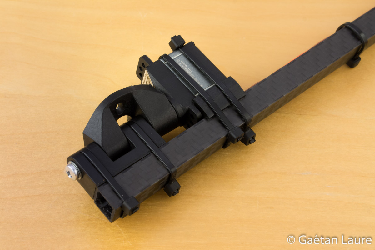
The tilt mechanism and the servo are mounted using zip-ties. Zip-ties act as a mechanical fuse to prevent damage in case of a crash.
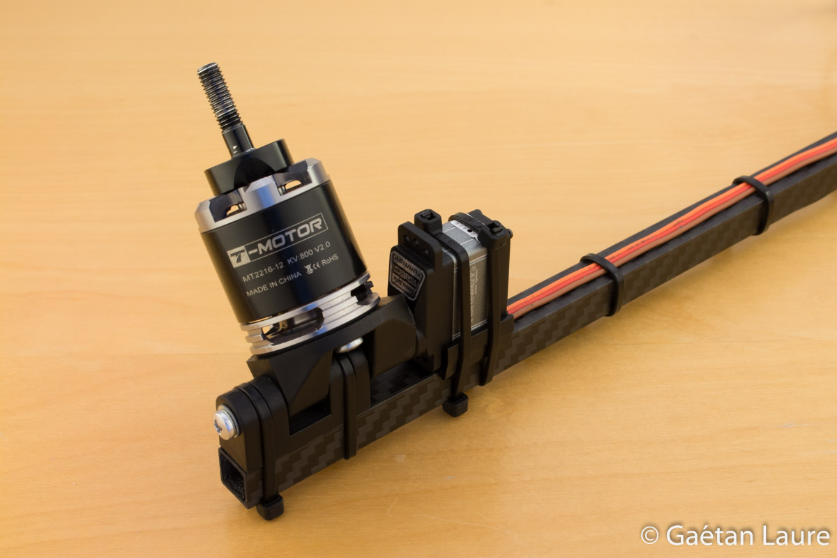
And finally the motor is mounted on the tilt mechanism with screws.
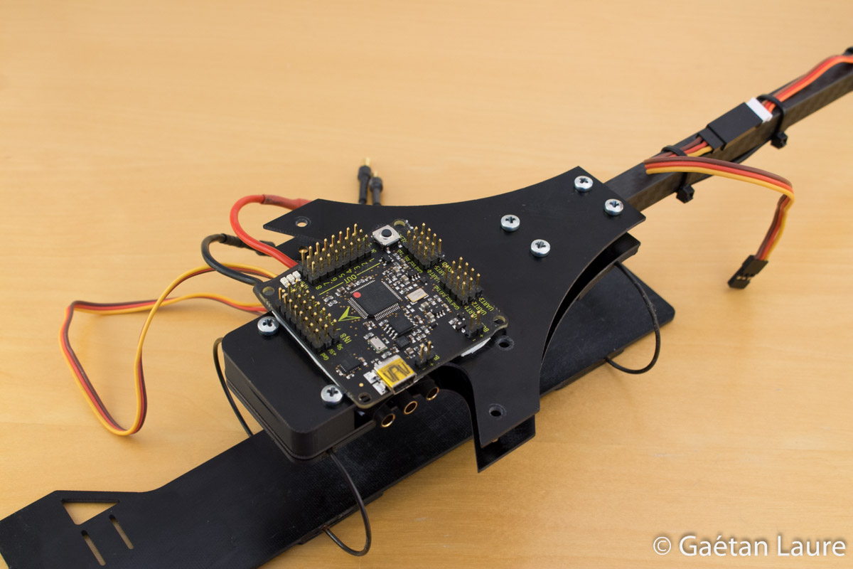
Let's now mount the main plates of the frame with the battery tray.
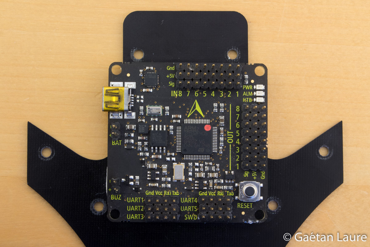
I first fit the flight controller to the top plate, using double sided tape.

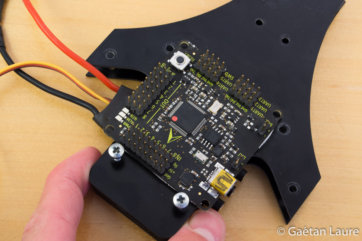
I'm putting double sided tape on the bottom plate to fit one ESC on it.
The ESC fitted on the bottom plate. It will remain between the two plates after assembly.
Now it's time to assemble the two plates.
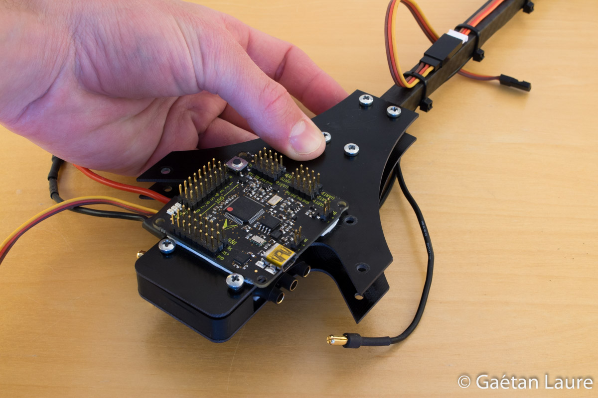
The 3D printed front spacer and the back arm come between the two plates.
The battery tray has to be attached under the bottom plate.

The battery tray and plates assembled.
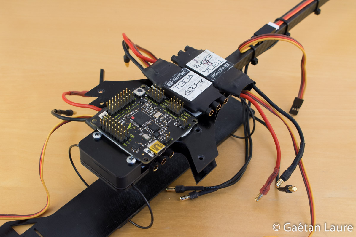
With double sided tape, I install the two remaining ESCs on the top plate.
Let's finally install the radio receiver.
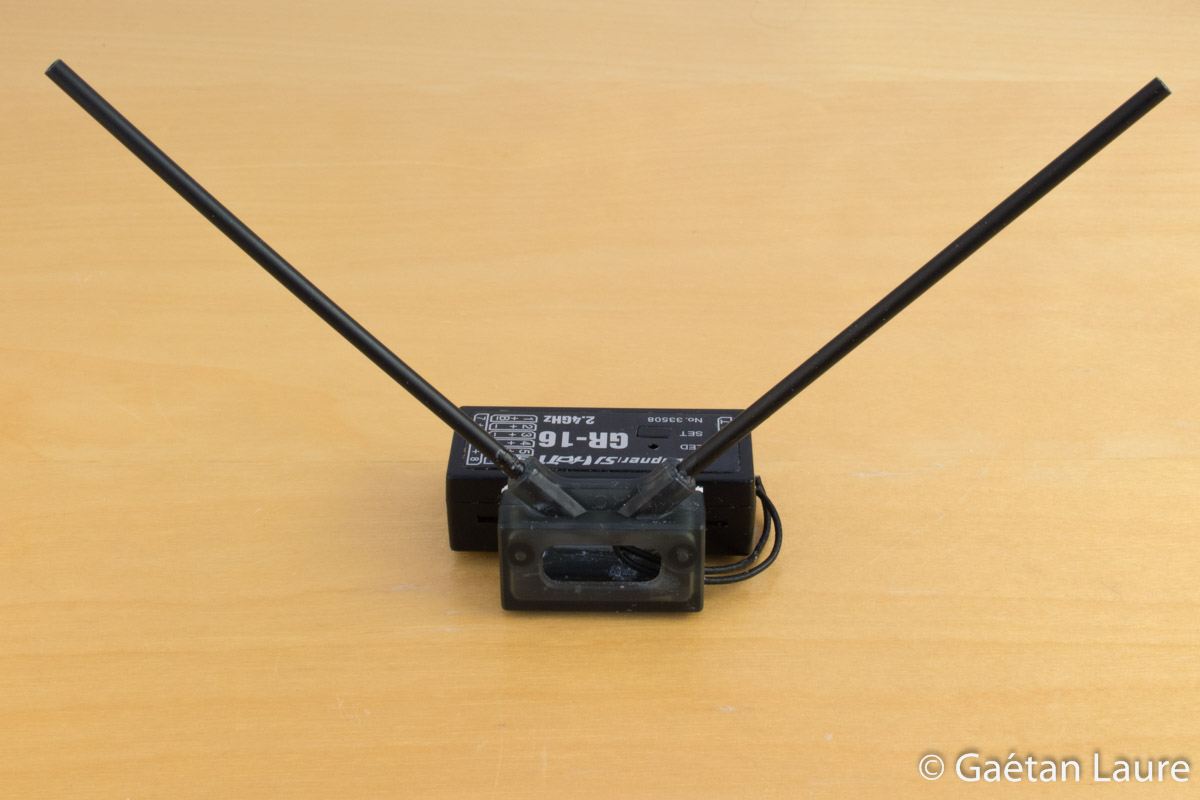
The two antennas are fitted into plastic tubes, oriented at 90 degrees to each other (to improve the received signal quality).
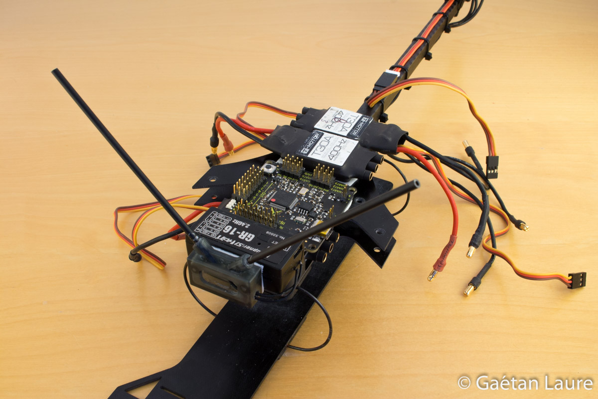
The receiver installed on the front of the top plate.
Finally, the two front arms are assembled between the two plates.
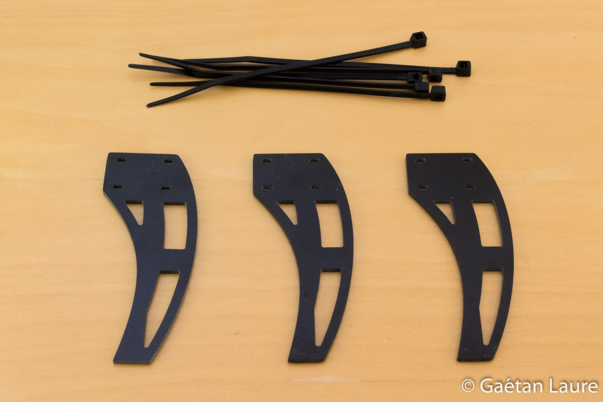
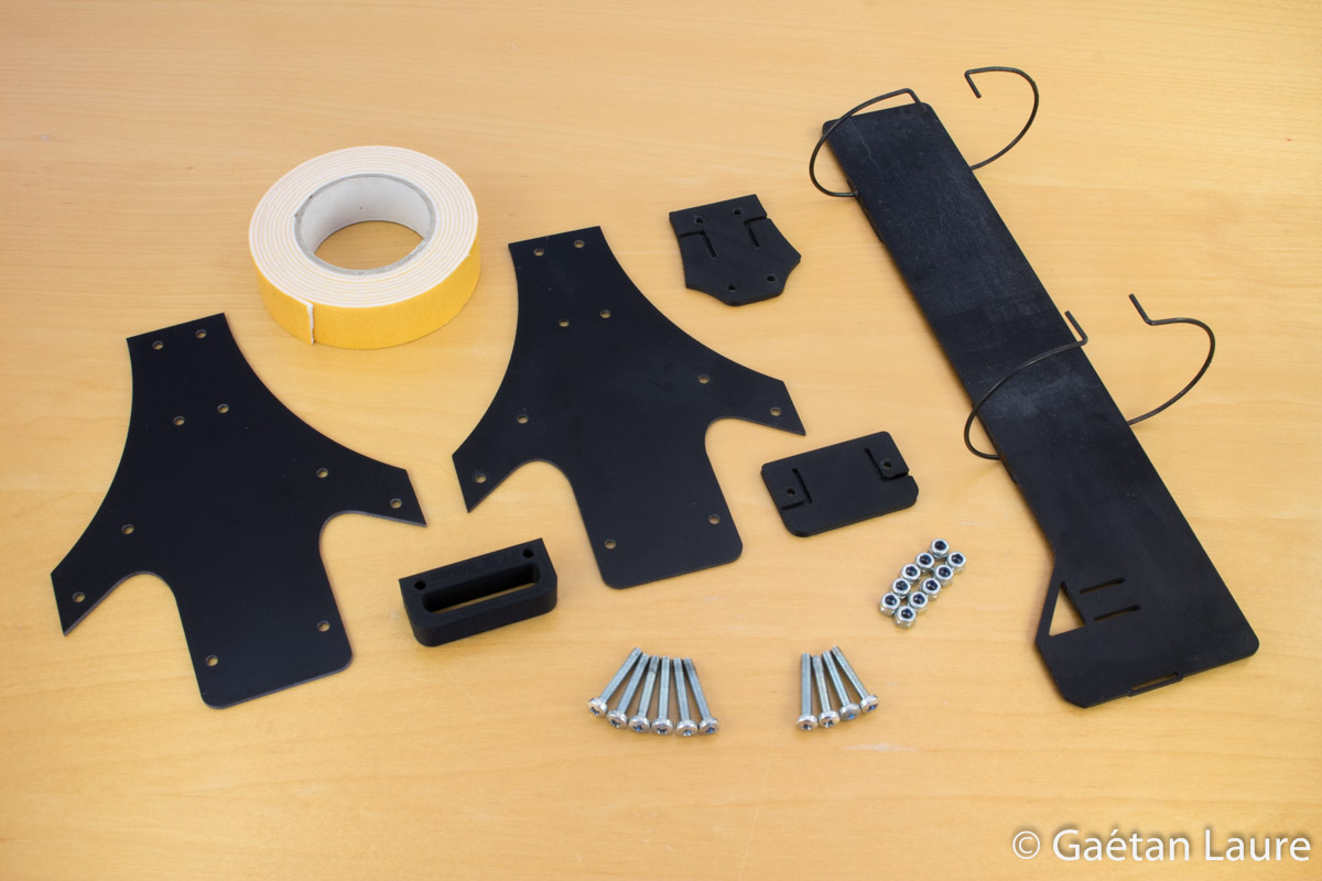
The landing gear.
The landing gear is attached with zip-ties.
Beginning to look like a tricopter!
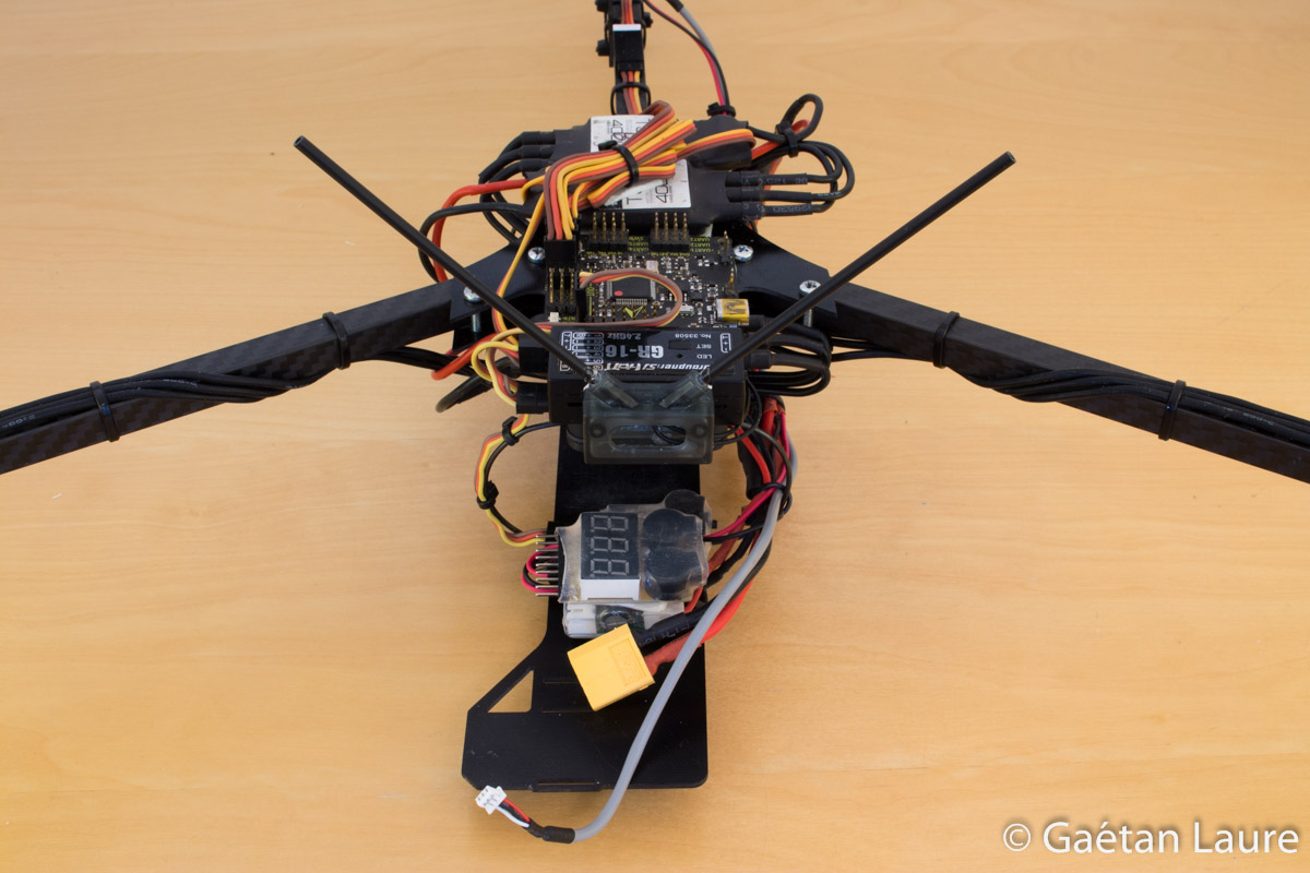
Now it's time to wire everything.

I adapted a wire module from Hobbyking to be able to power all the components of the drone from the LiPo battery. Le title component on the left is a "Lost Drone Alarm" from Hobbyking. It buzzes when the receiver signal send to the flight controller remain constant for more than one minute.
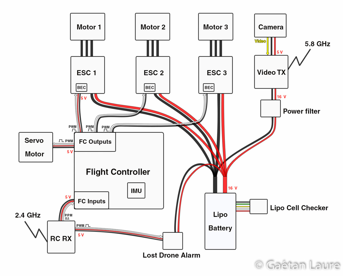
I have drawn this wiring diagram to clarify how components are connected.
FPV components are wired this way. The emitter is powered by the battery through the power filter (a RC circuit). The emitter features a converter to power supply the camera with the appropriate voltage (5V).
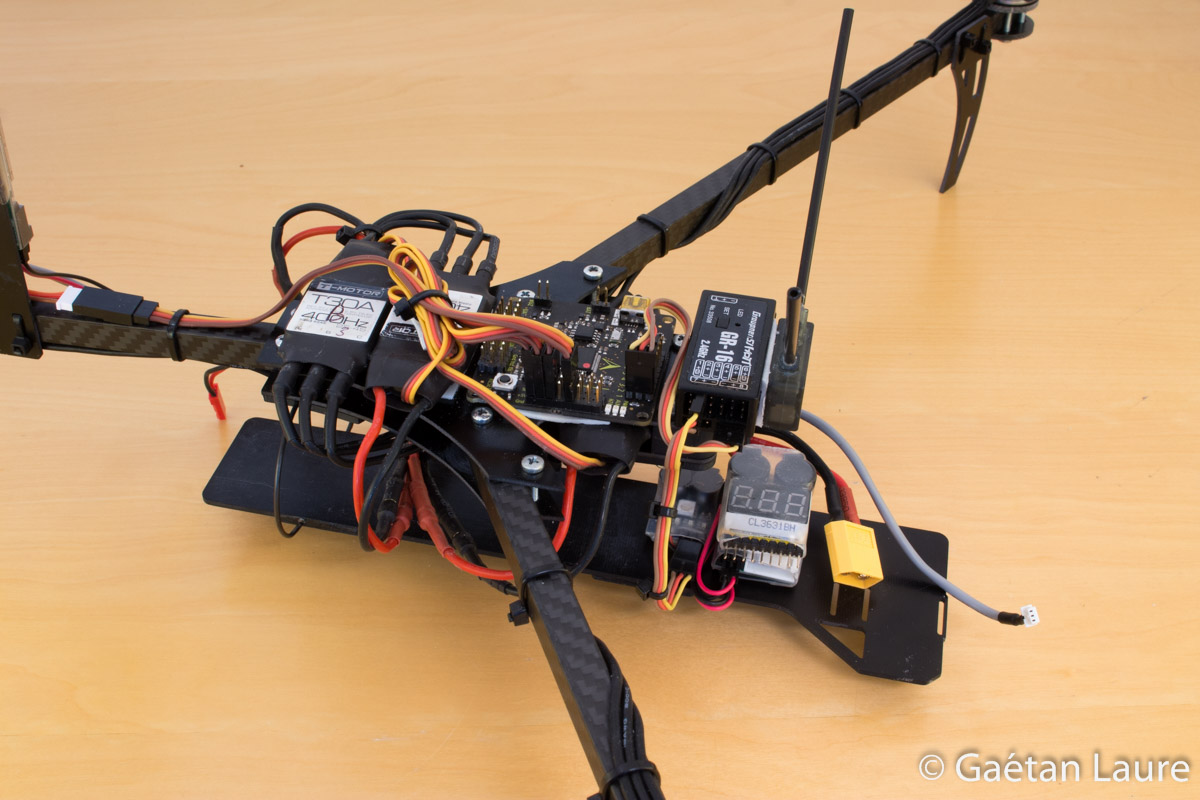
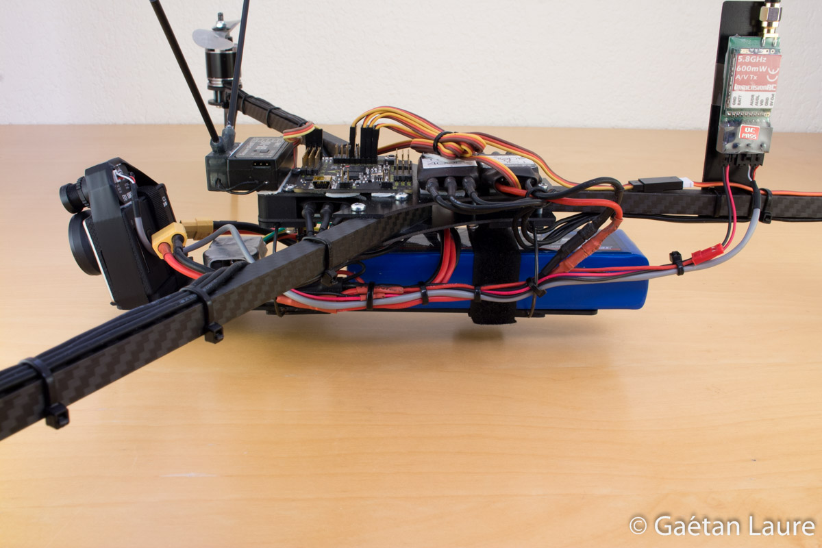
We install the video emitter (VTX) on the back arm of the tricopter.

The video emitter is attached using zip-ties.

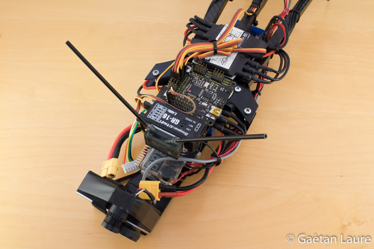
Organizing and connecting wires to power all the components.
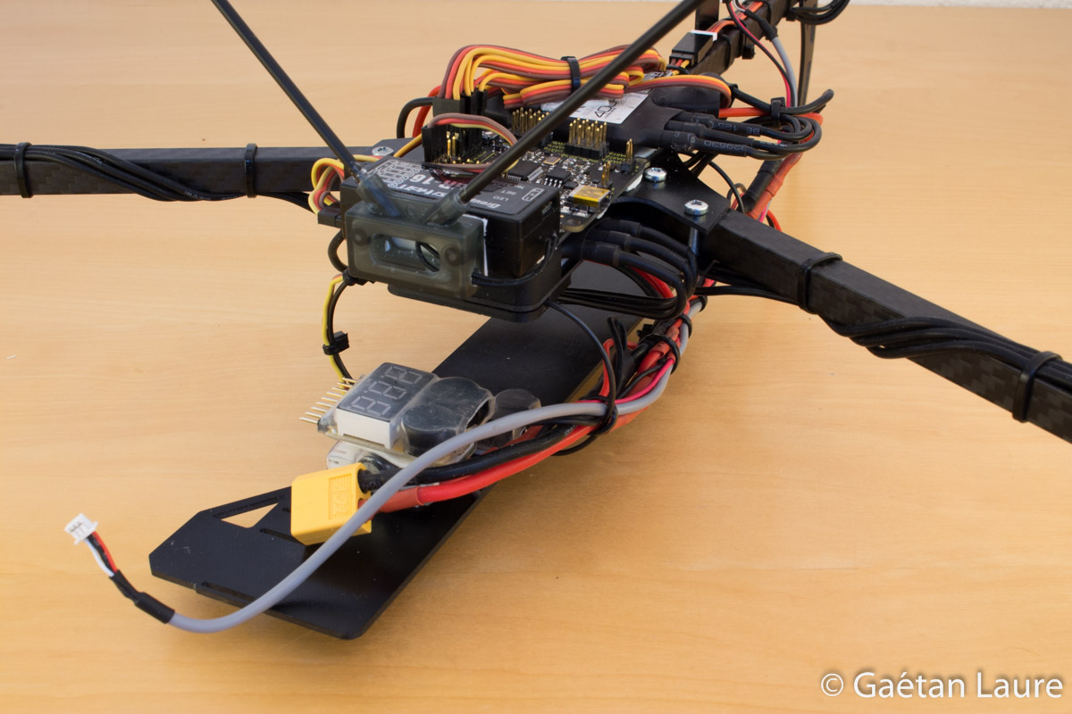
The LiPo cell checker, the "lost drone alarm" and the FPV power filter are positioned on the battery tray with double sided tape.
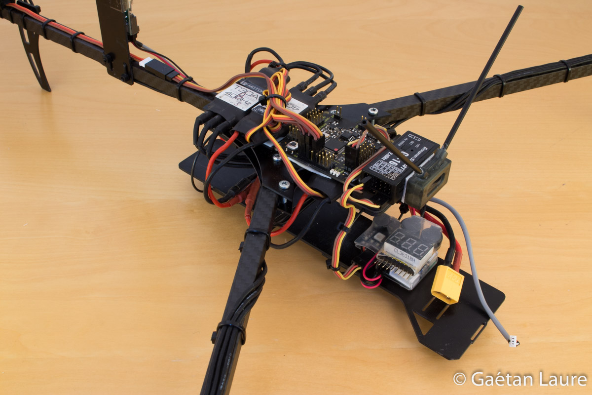
Only one wire (excluding positive and negative power wires) is connected between the radio receiver (RX) and the flight controller (FC). Indeed, all the radio channel information is transmitted through one PPM (Pulse Position Modulation) signal. One wire is also connected between the RX and the "drone lost alarm". It sends the information of one radio channel. If this information remains constant for more than one minute (meaning that the connection between the radio and the receiver has been lost), the alarm would buzzes.
The ESCs and the servo motor are connected to the FC outputs which are sending PWM (Pulse Width Modulation) signals.
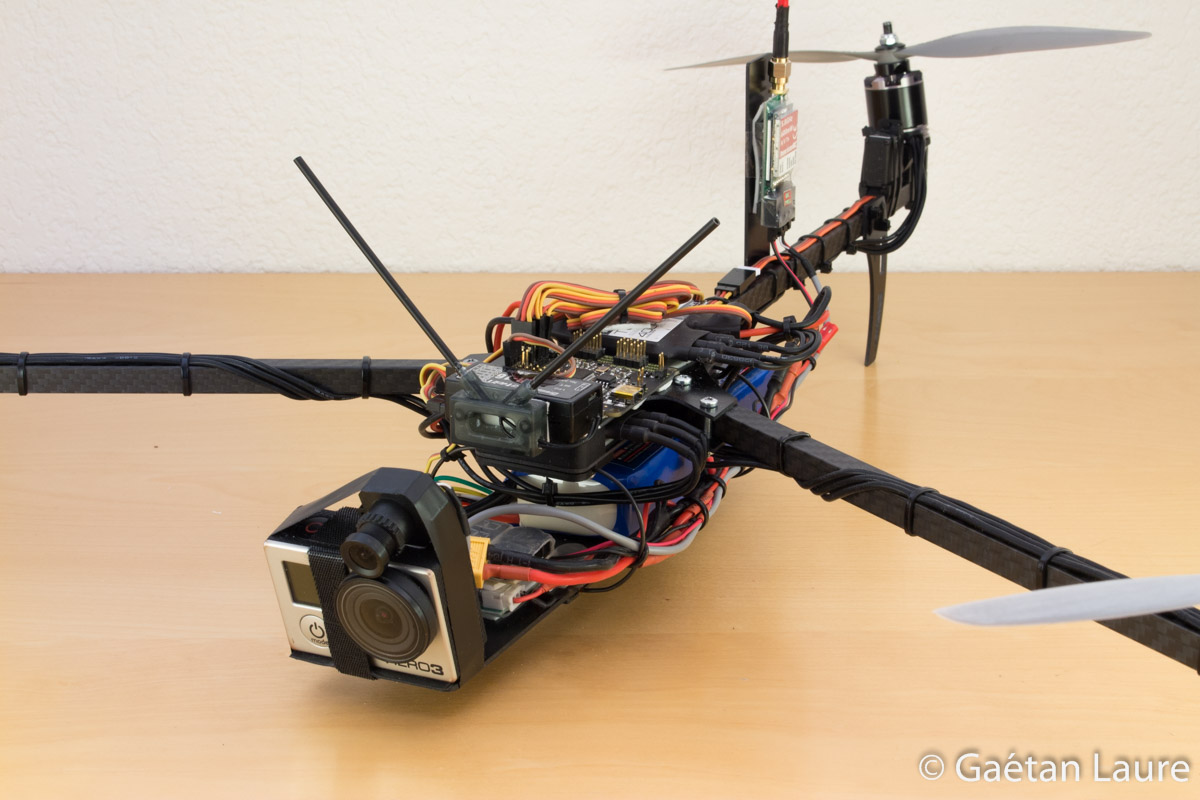
Now we just have to mount the cameras and the props to finish the build.
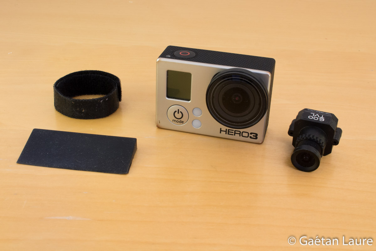
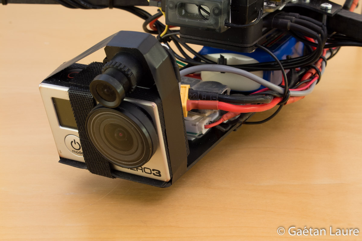
The camera used for recording video is a GoPro Hero 3 Black. The FatShark camera is used for FPV. We are going to attach them on the battery tray with Velcro and tape.
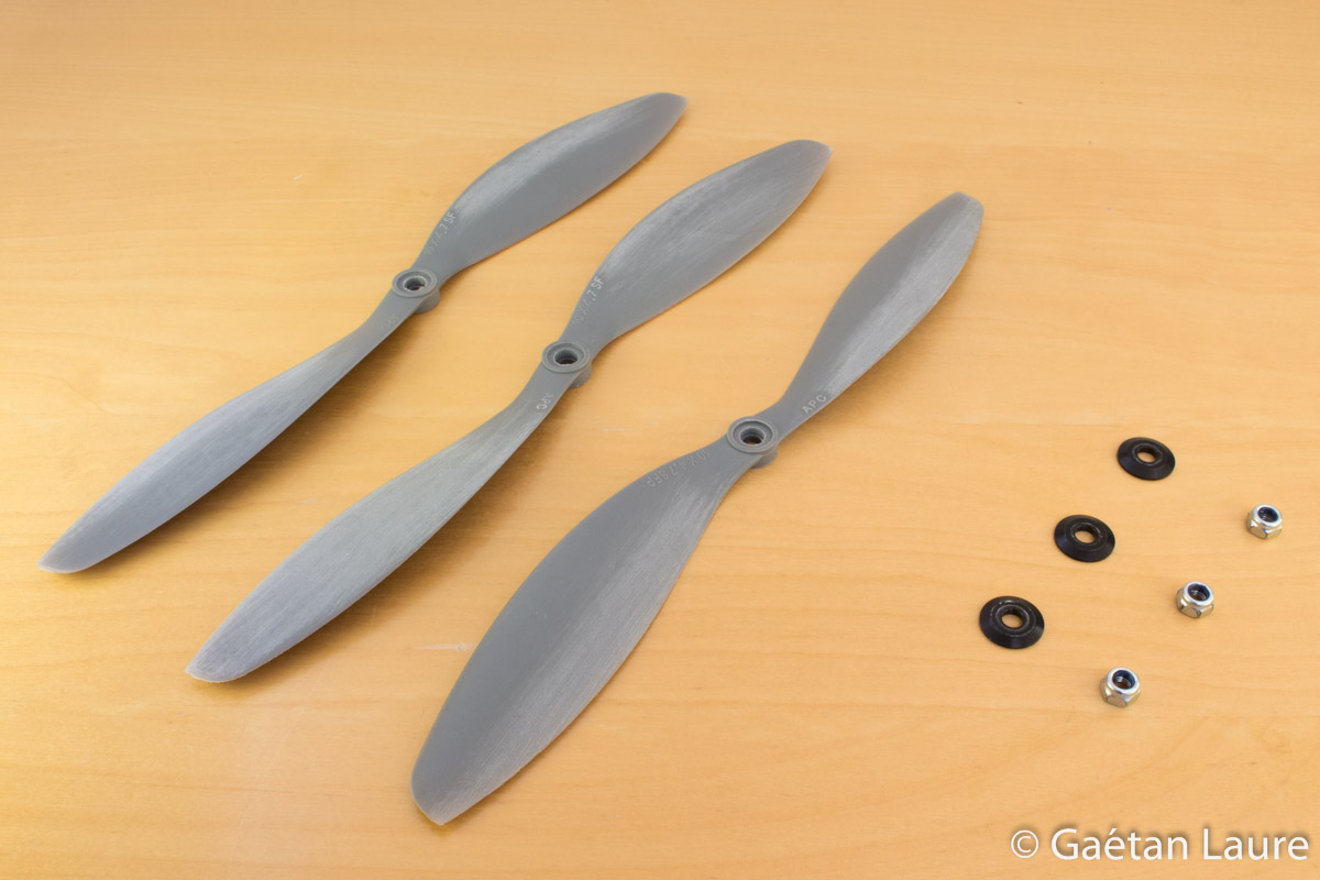
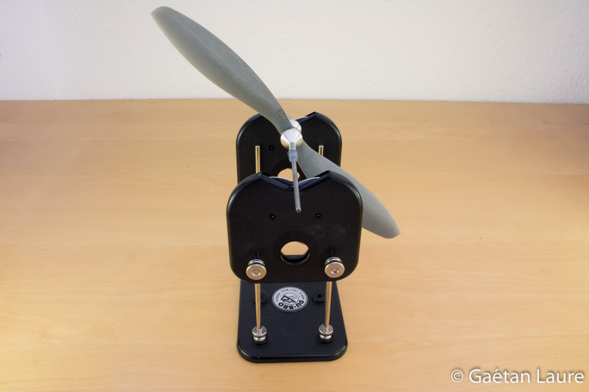
I used 10x4.7" Slow Fly props.
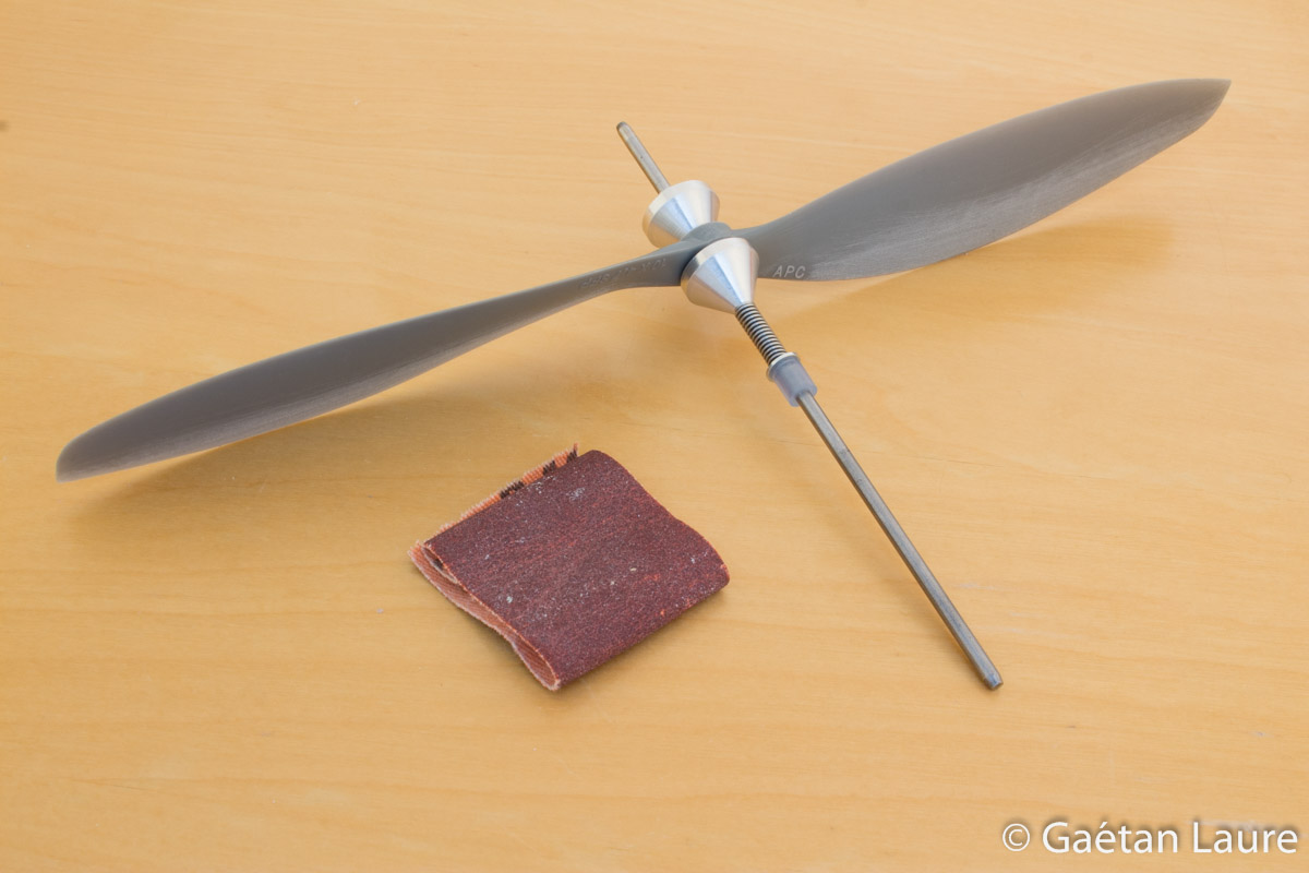
To balance the props, I remove a bit of material by sanding them with sandpaper.
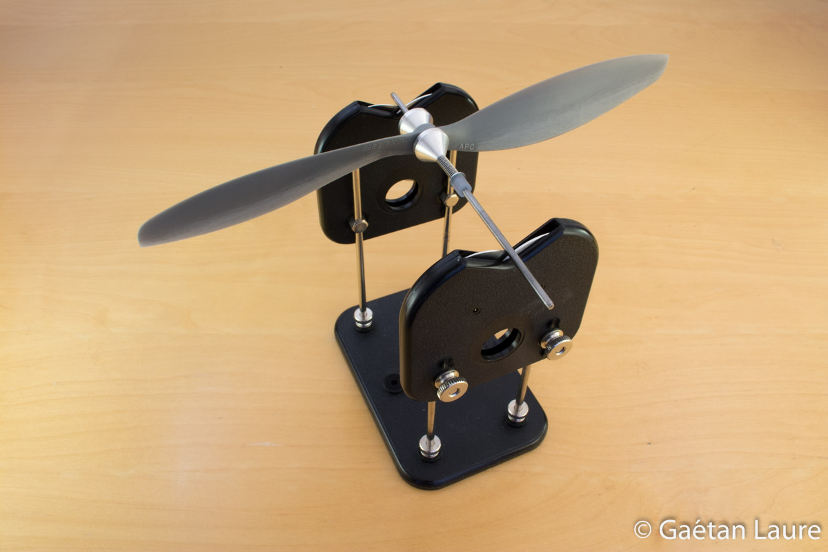
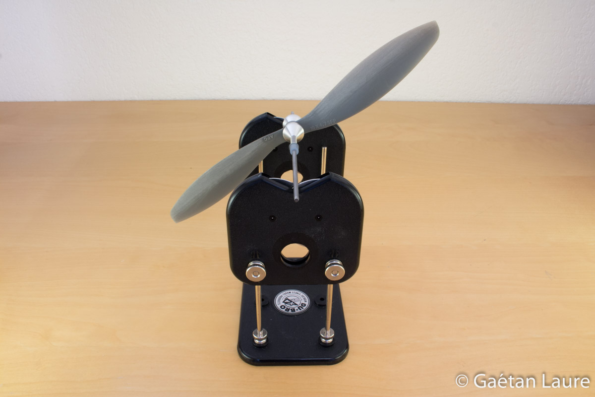
I use the Du-Bro balancer. The prop is well balanced when it remains steady in all the positions.
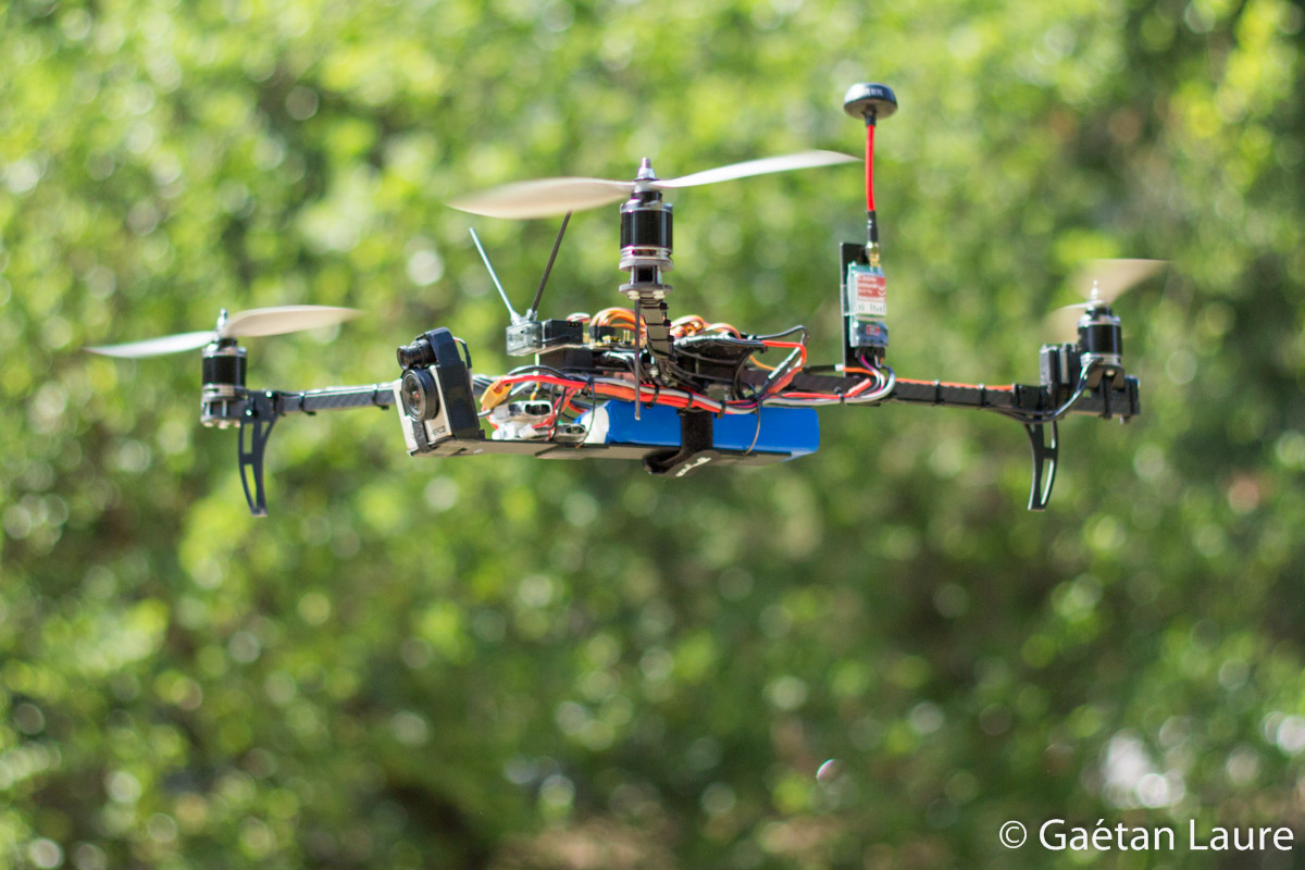
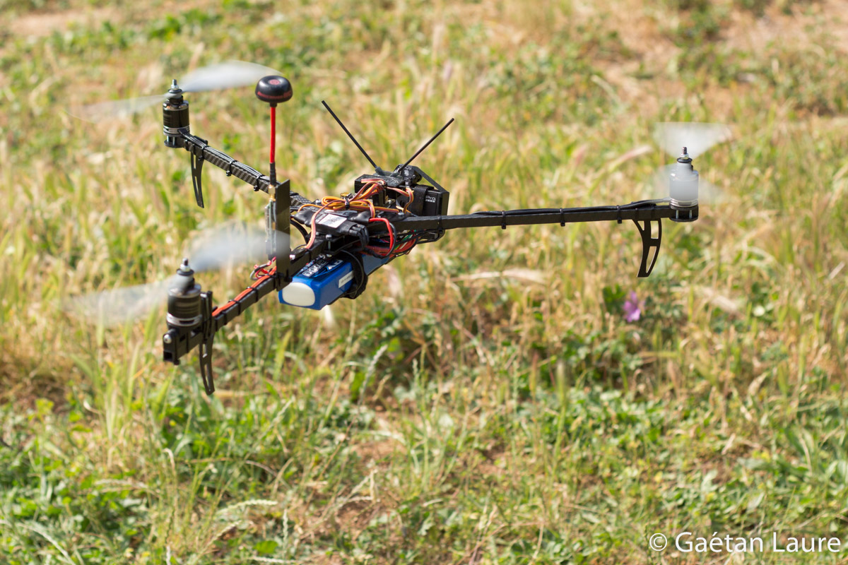
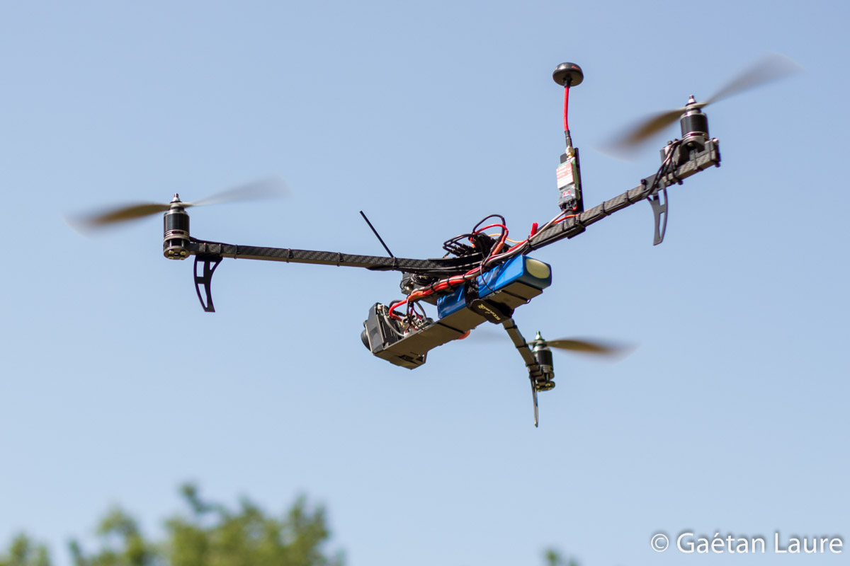
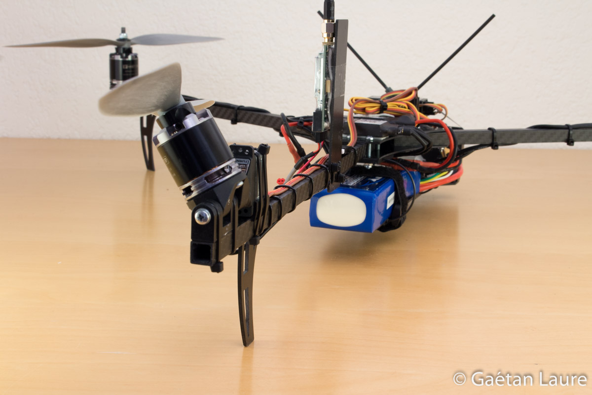
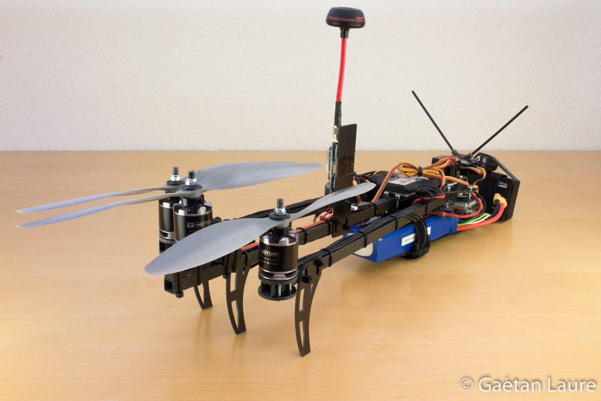
The tricopter is finally fully mounted! Some pictures of the result.

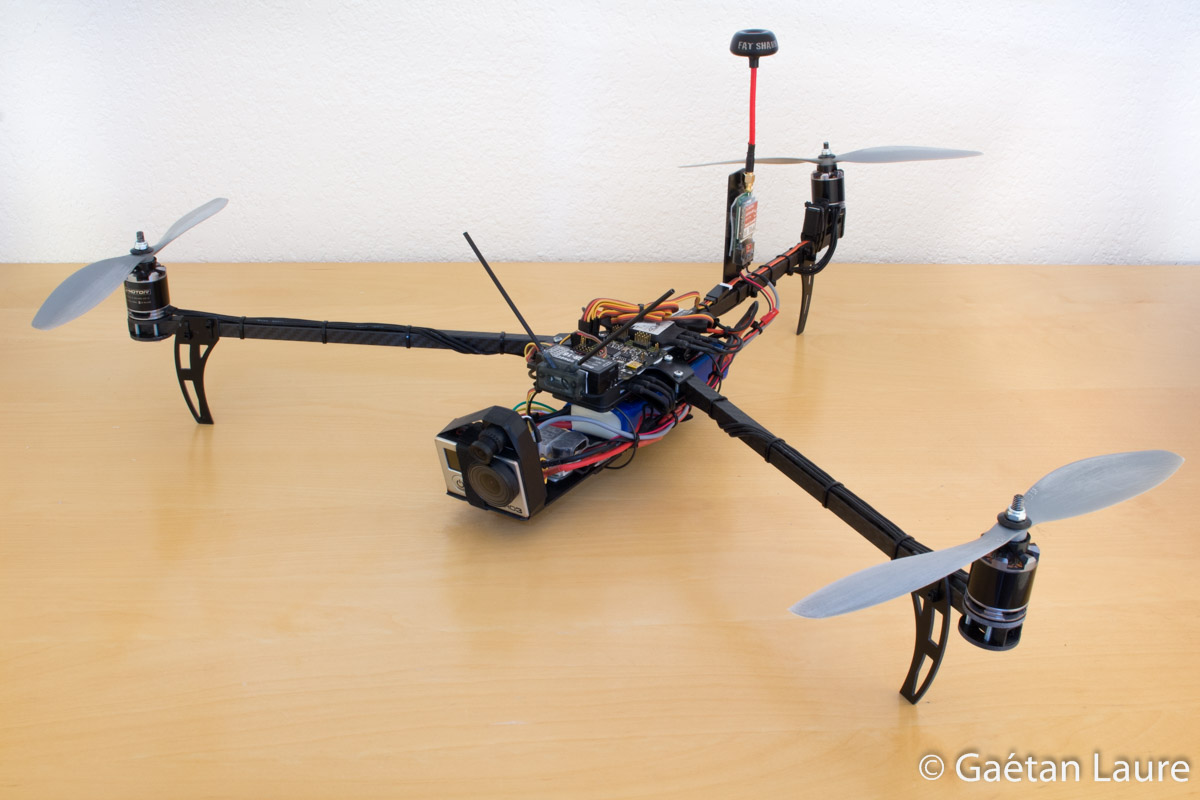
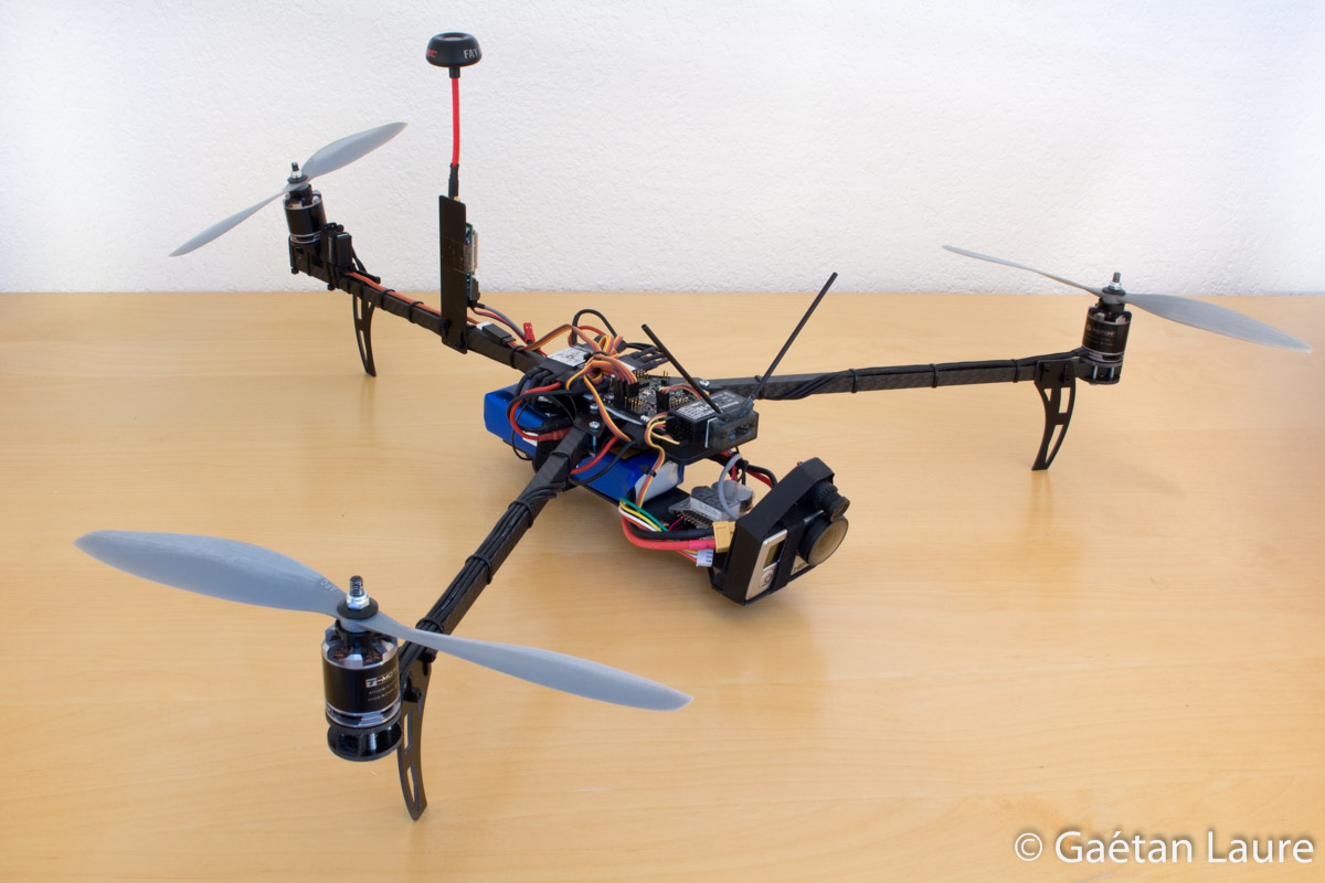
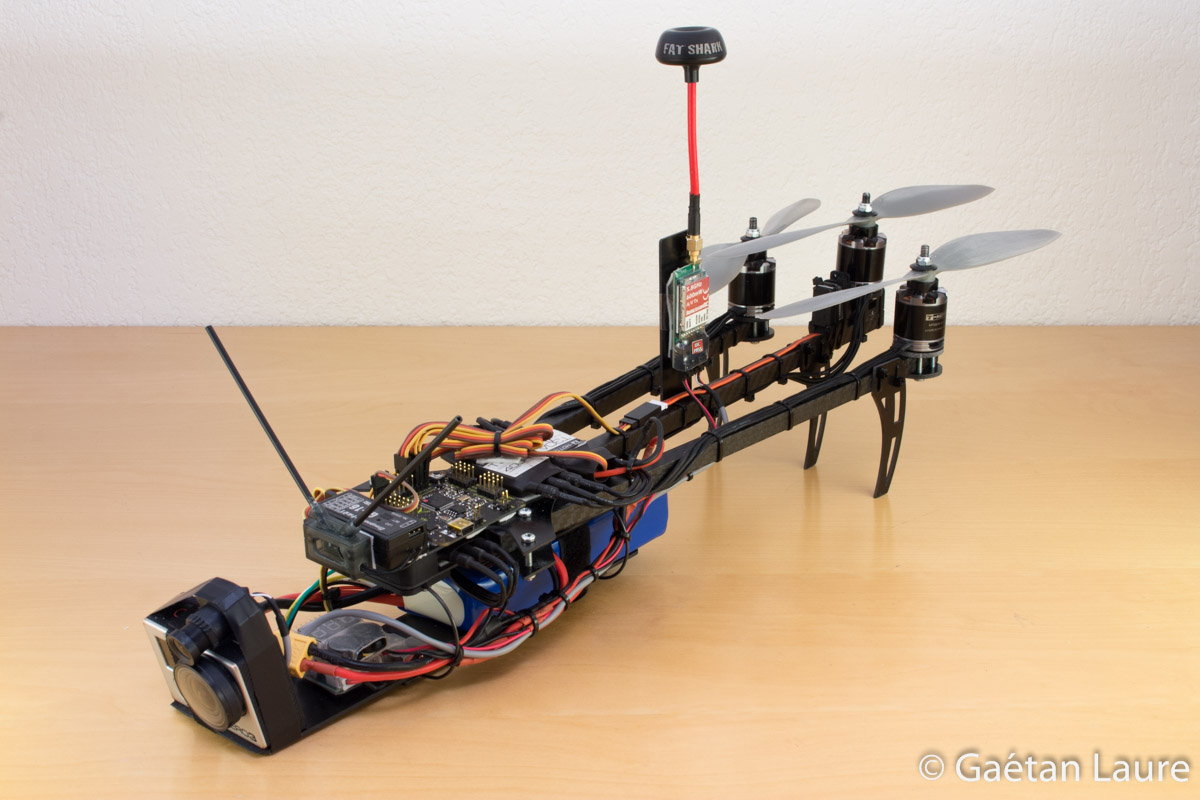
The tricopter can be folded up for easy transportation.
It's time for the first flight!
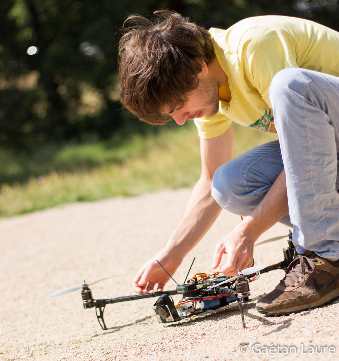

The tricopter, ready to takeoff.
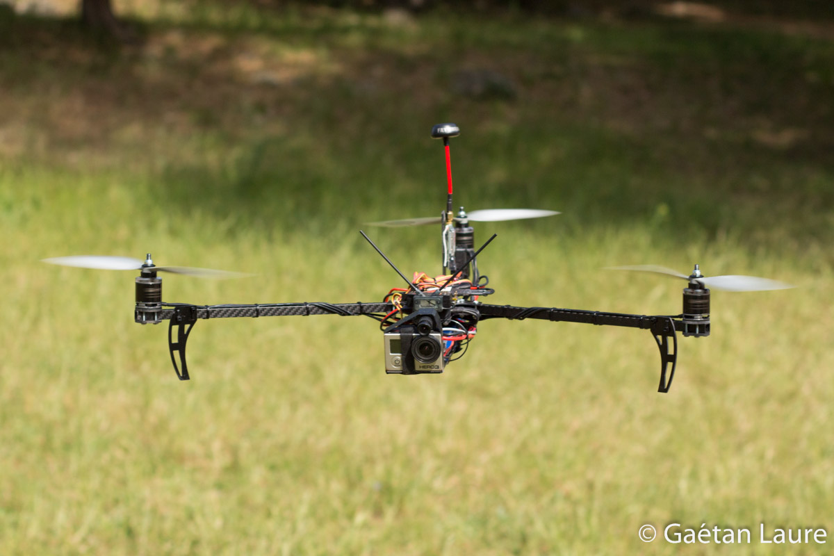
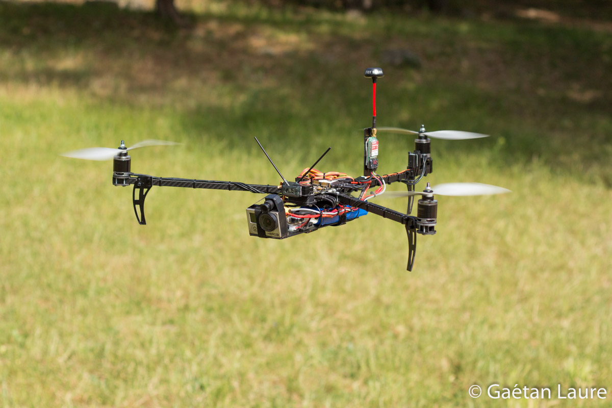
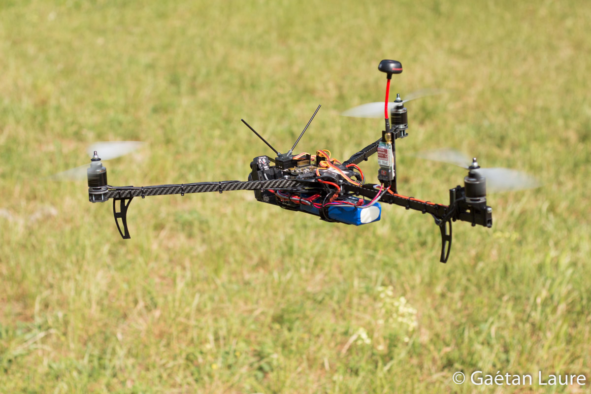


FPV flying!